
TM 5-3805-280-24-2
Cooling System
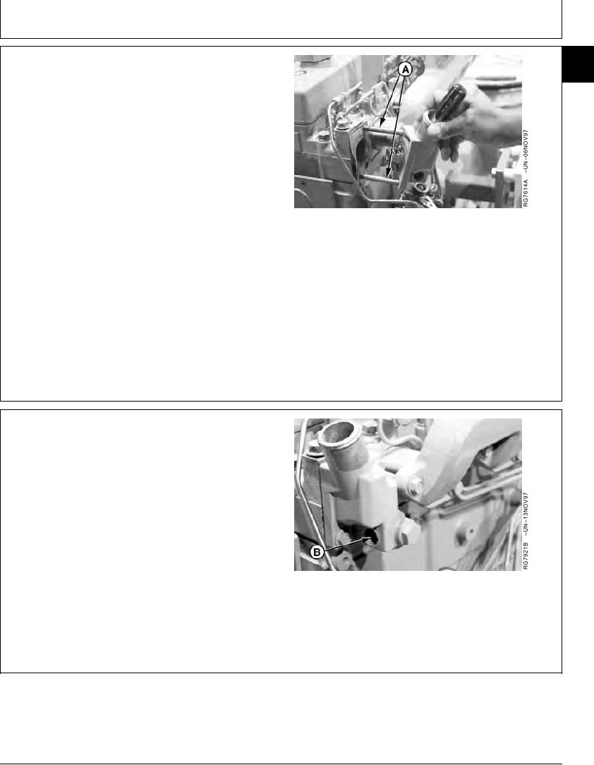
INSTALL WATER MANIFOLD/THERMOSTAT
25
7
COVER AND THERMOSTAT
IMPORTANT: Install manifold gasket so that smaller
(round) holes are at lower left and
upper right corners of manifold
(matching studs A).
1. Using guide studs (A) to keep gasket in place, install a
new gasket on cylinder head.
NOTE: Thermostat must be installed with jiggle wire
facing up in the 12 o'clock position.
A--Guide Studs
2. Using a screwdriver to hold thermostat in place, install
thermostat and water manifold/thermostat cover.
Tighten cover cap screws to specifications.
Water Manifold/Thermostat Cover (Single Thermostat)--
Specification
Torque ............................................................................. 70 Nm (52 lb-ft)
RG,25,JW7559
1920NOV971/3
3. Lubricate new O-ring with PT507 Multi-Purpose
Grease. Install seal (B) in thermostat cover.
B--Seal
Continued on next page
RG,25,JW7559
1920NOV972/3
13-330