
TM 5-3805-280-24-2
Fuel System
35
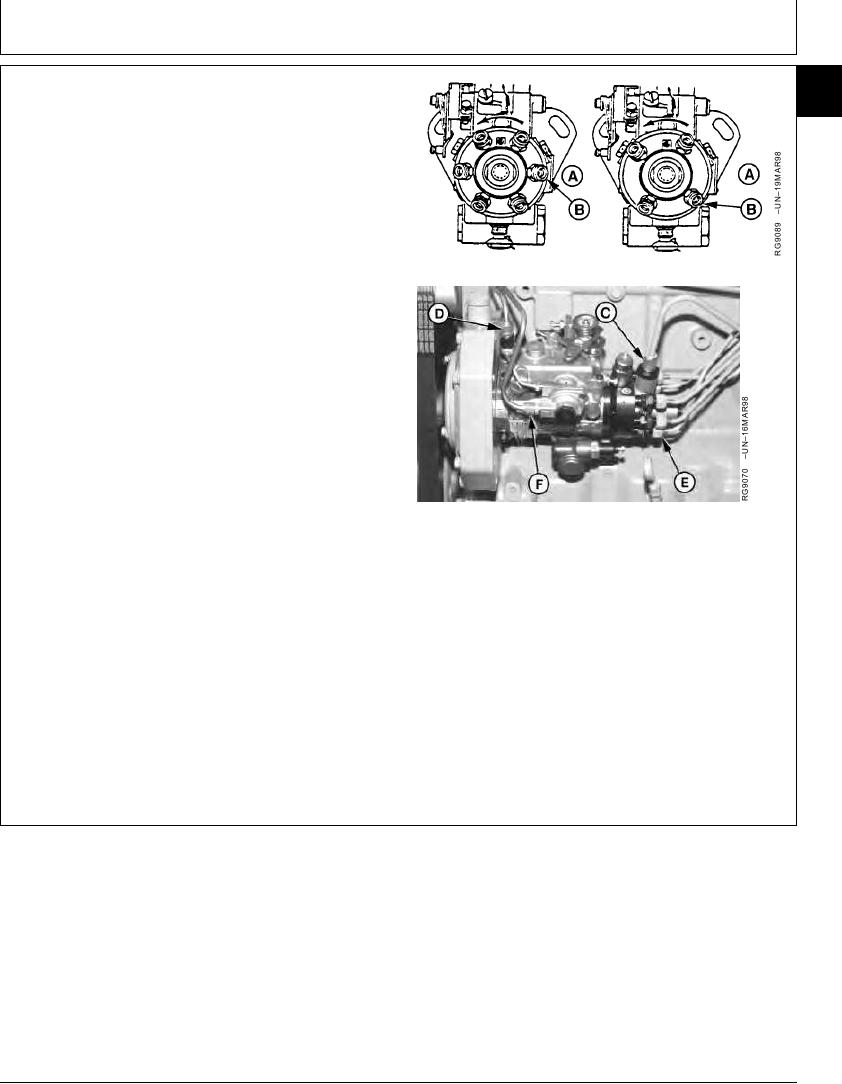
11. Connect injection pump pressure lines (E). Beginning
47
with outlet (B) and continue around the pump head in
counterclockwise direction, attaching lines in same
order as engine firing (1-5-3-6-2-4 on 6-cylinder
engines and 1-3-4-2 on 4-cylinder engines).
12. Tighten fuel delivery (pressure) lines at pump to
specifications, using a suitable 17 mm deep-well
socket.
6-Cyl Engine (Left) 4-Cyl Engine (Right)
Fuel Injection Pump Delivery Lines--Specification
Torque ............................................................................. 27 Nm (20 lb-ft)
IMPORTANT: ALWAYS use a backup wrench when
loosening or tightening fuel delivery
lines at fuel injection pump, so that the
pump discharge fittings are not altered.
This prevents possible internal pump
damage.
13. Connect fuel supply line (C), fuel return line (D) and
aneroid line (F).
14. Connect fuel shut-off cable and speed control linkage,
if equipped. Install and securely tighten electrical
A--Engine Block Side
B--Outlet Connection to No. 1 Cylinder
connections to shut-off solenoid and throttle
C--Fuel Supply Line
positioning solenoid, if equipped. Connect cold start
D--Fuel Return Line
switch, if equipped.
E--Fuel Delivery (Pressure) Lines
F--Aneroid Line
15. Bleed air from fuel system as outlined in Group 115.
Start engine, run for several minutes and check entire
fuel system for leaks.
RG,35,JW7603
1920NOV975/5
13-426