
TM 5-3805-280-24-2
Fuel System
35
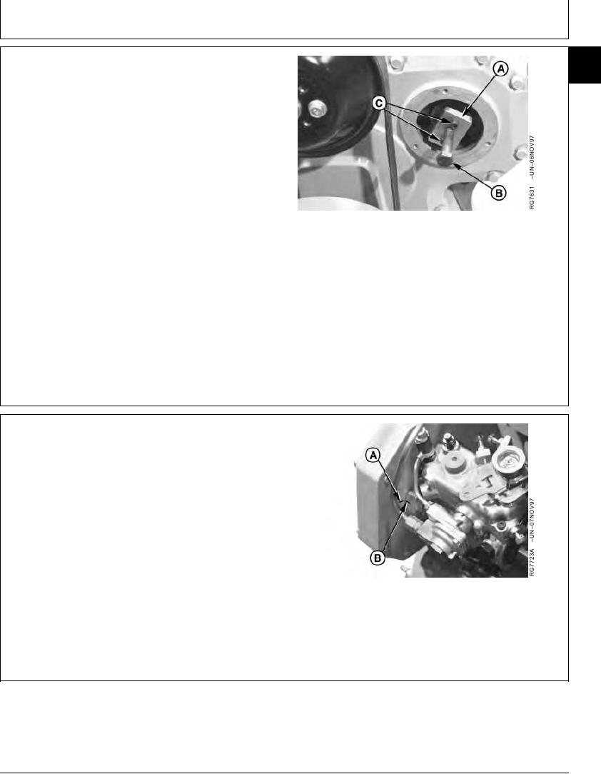
NOTE: The injection pump drive gear fits snugly onto a
43
tapered drive shaft and is indexed by a Woodruff
key installed in drive shaft. Use JDG670A Drive
Gear Puller (A) to remove drive gear from shaft.
6. Attach JDG670A Drive Gear Puller to injection pump
drive gear as shown. Follow instructions provided with
tool set.
NOTE: Replace 6 mm, Grade 12.9 cap screws (C) as
needed.
7. Evenly tighten the two 6 mm, Grade 12.9 screws
A--Drive Gear Puller
(threaded in drive gear) and snugly tighten center
B--Forcing Screw
forcing screw (B) against end of pump shaft.
C--Cap Screws
8. Tighten center forcing screw until pump drive gear is
free from tapered shaft. Remove JDG670A Puller from
drive gear.
RG,35,JW7605
1920NOV973/4
9. Check to make sure that timing marks on back side of
front plate (A) and injection pump flange (B) are
present and properly aligned. This assures that
repaired or replacement pump can be properly timed to
engine when installed.
If timing mark is not clearly visible on front plate, scribe
a visible reference mark as accurately as possible
in-line with mark on pump flange.
10. Remove injection pump mounting stud nuts. Remove
injection pump from mounting studs.
A--Timing Mark on Front Plate
B--Timing Mark on Injection Pump
RG,35,JW7605
1920NOV974/4
13-422