
TM 5-3805-280-24-2
Fuel System
35
IMPORTANT: Do NOT overtighten cap screws on
40
pump cover plate to avoid damage to
O-ring.
8. Install access cover plate using a new O-ring, if
needed. Apply LOCTITE 242 (TY9370) to cap screw
threads and tighten to specifications.
Rotary Injection Pump Front Access Plate Cap Screws--
Specification
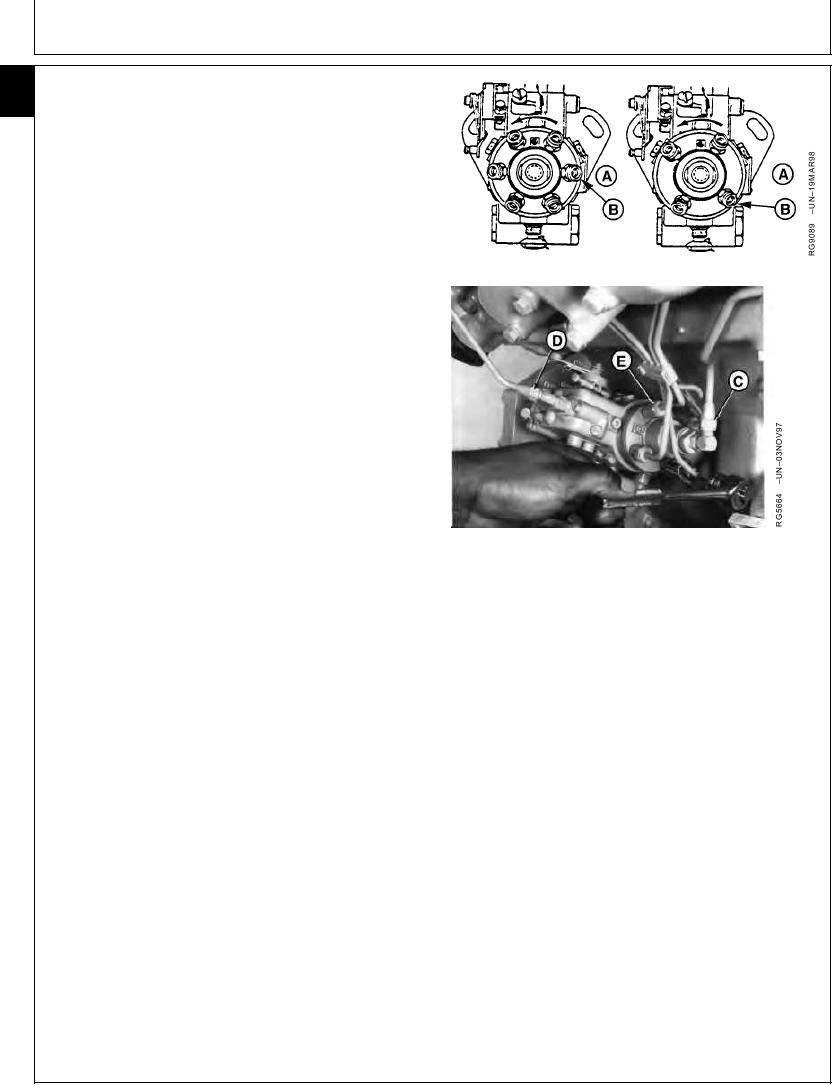
6-Cyl Engine (Left) 4-Cyl Engine (Right)
Torque .............................................................. 2 Nm (1.7 lb-ft) (20 lb-in.)
9. Align timing mark on pump flange with timing mark on
front plate.
10. Tighten three hex nuts securing the pump to the front
plate to specifications.
Rotary Injection Pump Mounting Nuts--Specification
Torque ............................................................................. 27 Nm (20 lb-ft)
11. Connect injection pump pressure lines (E). Beginning
with outlet (B) and continue around the pump head in
counterclockwise direction, attaching lines in same
order as engine firing (1-5-3-6-2-4 on 6-cylinder
engines and 1-3-4-2 on 4-cylinder engines).
A--Engine Block Side
B--Outlet Connection to No.1 Cylinder
C--Fuel Supply Line
12. Tighten fuel delivery (pressure) lines at pump to
D--Fuel Return Line
specifications, using a suitable 17 mm deep-well
E--Fuel Delivery (Pressure) Lines
socket.
Fuel Injection Pump Delivery Lines (At Pump)--Specification
Torque ............................................................................. 27 Nm (20 lb-ft)
IMPORTANT: ALWAYS use a backup wrench when
loosening or tightening fuel delivery
lines at fuel injection pump, so that the
pump discharge fittings are not altered.
This prevents possible internal pump
damage.
13. Connect fuel supply line (C) and fuel return line (D).
LOCTITE is a registered trademark of Loctite Corp.
Continued on next page
RG,35,JW7606
1920NOV973/4
13-419