
TM 5-3805-280-24-2
Fuel System Operation and Tests
INSTALL JT07158 (OR FKM10429A) TIME TRAC KIT:
115
17
IMPORTANT: All transducers and sensors must be
installed at nozzle end of No. 1 fuel
injection line. If access to No. 1 line is
restricted, sensor can be installed on
No. 4 injection line (4-cylinder engines)
and No. 6 injection line (6-cylinder
engines).
Remove all paint from injection line
where clamp-on transducer will be
installed and be sure this location is
thoroughly clean.
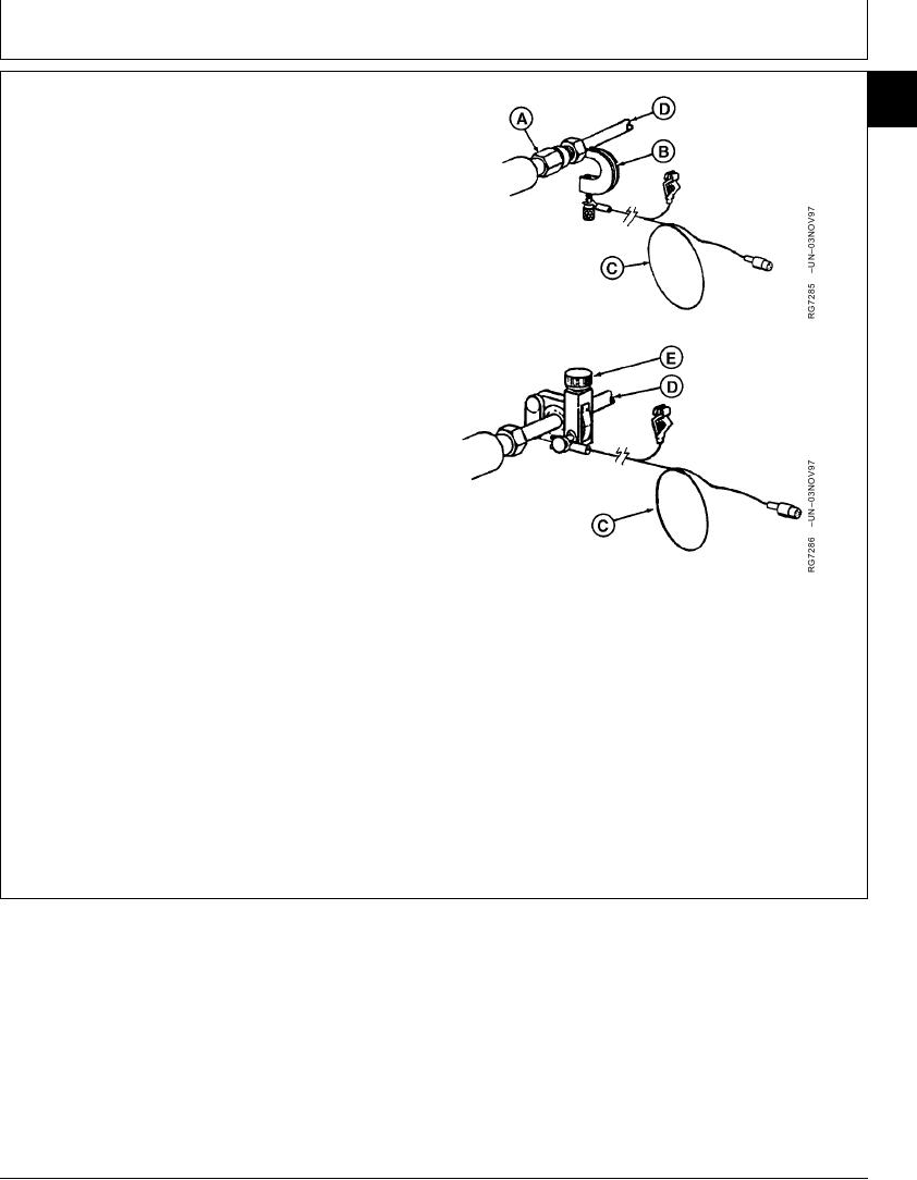
1. On engines with optional JT07155 In-Line SOI Sensor
(A) installed between injection nozzle and fuel delivery
line, install JT07173 SOI Clamp Assembly (B) onto
clean sensor and tighten securely.
2. On engines without optional JT07155 In-Line Sensor,
install JT07177 6 mm (green) Clamp-on Transducer
(E) onto clean, paint-free injection line and tighten
securely.
3. Assemble red lead of JT07172 Transducer Cable (C)
A--JT07155 In-Line SOI Sensor
onto in-line sensor or transducer, however equipped.
B--JT07173 SOI Clamp Assembly
C--JT07172 Transducer Cable
4. Attach spring clip to a solid ground. Plug connector into
D--Fuel Injection (Delivery) Line
JT07170 meter port marked SR.
E--JT07177 6 mm (Green) Clamp-On Transducer
TIME TRAC is a registered trademark of Stanadyne Automative Corp.
Continued on next page
RG,115,JW7711 1924NOV972/9
13-544