
TM 5-3805-280-24-2
Fuel System Operation and Tests
CHECK AND ADJUST IN-LINE INJECTION
115
23
PUMP STATIC TIMING
1. Using JDE83 or JDG820, rotate engine flywheel (in
normal running direction) until No. 1 piston is at "TDC"
of it's compression stroke. At this point, JDE81-4
Timing Pin should enter hole in flywheel.
2. Remove injection pump drive gear cover and O-ring.
3. Look through the drive gear timing hole to see if the
timing hole in the injection pump hub is visible. If it
isn't, remove JDE81-4 Timing Pin from flywheel and
rotate the engine ( in normal running direction) one
more revolution and reinstall timing pin in flywheel.
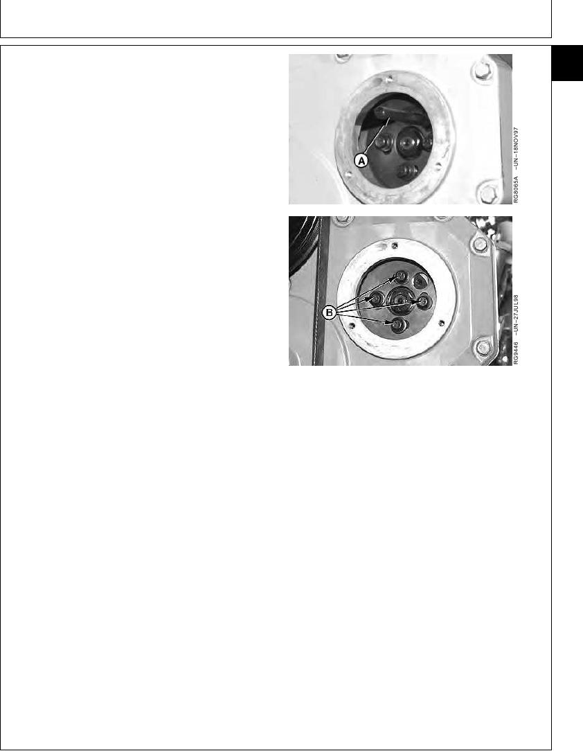
4. Attempt to install JDG886 Injection Pump Timing Pin
(A) through injection pump drive gear into injection
pump hub unitil it bottoms out. It may be necessary to
rotate the pump drive hub slightly to get the pin
installed. If pin can be installed, injection pump is
correctly timed.
5. If timing pin won't engage in injection pump drive gear
into injection pump hub, loosen drive gear-to-pump hub
cap screws (B) and rotate hub slightly until timing pin
A--Timing Pin
will fully engage.
B--Gear-to-Hub Cap Screws
6. Tighten drive gear-to-pump hub cap screws to
specifications.
In-Line Injection Pump Drive Gear-to-Pump Hub Cap Screws--
Specification
Torque ............................................................................. 47 Nm (35 lb-ft)
7. Remove JDG886 Injection Pump Timing Pin from
injection pump hub.
8. Install injection pump drive gear cover using a new
O-ring, if needed. Tighten cap screws to specifications.
In-Line Injection Pump Drive Gear Cover--Specification
Torque .............................................................. 5 Nm (3.7 lb-ft) (44 lb-in.)
9. Remove JDE81-4 Timing Pin from flywheel.
DPSG,OUO1004,254
1917JUL981/1
13-550