
TM 5-3805-280-24-2
Fuel System Operation and Tests
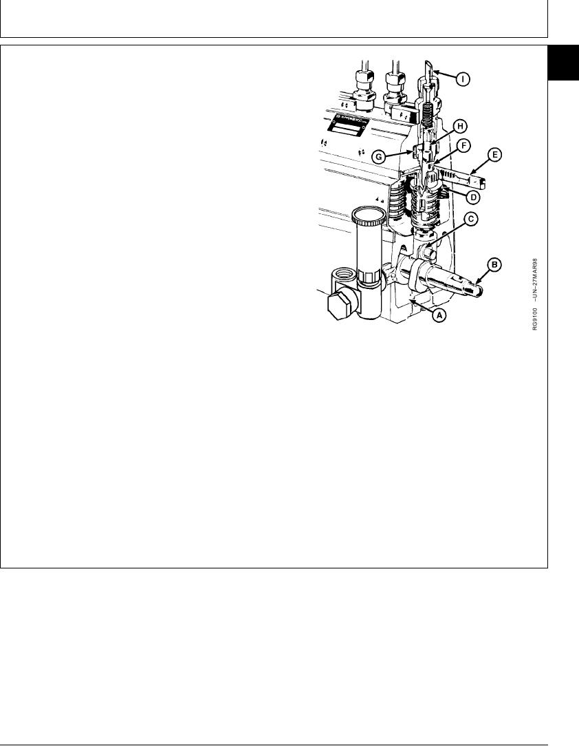
IN-LINE FUEL INJECTION PUMP OPERATION
115
69
Filtered fuel under pressure by the supply pump fills the
injection pump fuel gallery (G). As the camshaft rotates,
roller tappets (C) riding on the camshaft (B) lobes operate
the plungers (F) to supply high pressure fuel through the
delivery valves (H) to the injection nozzles.
A governor-operated control rack (E) is connected to the
control sleeves (D) and plungers to regulate the quantity
of fuel delivered to the engine.
Engine lubricating oil is piped to the injection pump
crankcase (A) to provide splash lubrication of the working
parts. Two drain holes at the front end of the pump
determine the level of oil maintained in the crankcase.
Excess oil drains out these holes and returns back to the
engine through the timing gear housing.
A--Crankcase
B--Camshaft
C--Roller Tappet
D--Control Sleeve
E--Control Rack
F--Plunger
G--Fuel Gallery
H--Delivery Valve
I--Delivery Pipe
RG,115,JW7688 1924NOV971/1
13-596