
TM 5-3805-280-24-2
Group 05
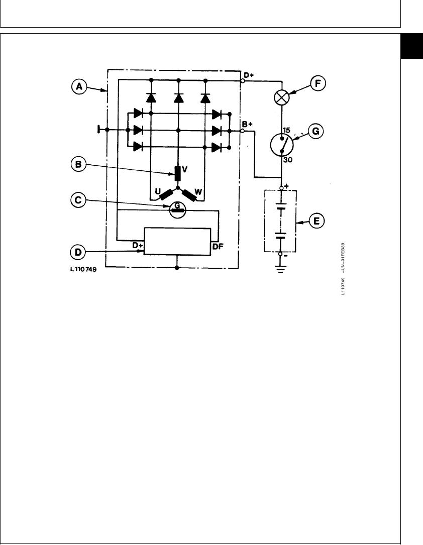
Robert Bosch Theory of Operation
30
FUNCTION OF ALTERNATOR
05
1
A--Alternator
D--Regulator
F--Alternator Indicator
G--Starting Motor Switch
B--Current Coil (Stator)
E--Battery
Light
C--Exciting Coil (Rotor)
the rectifier diodes. The current flows through the
The Bosch 14-volt alternator is a 12-pole, self-induced
diode and terminal B+ directly to the positive pole of
synchronous generator. The current coil is located in
the battery.
the stator, and the exciting coil in the rotor. The
exciting current is supplied by the rectifier (terminal
Alternator current is generated in each stator coil (B) of
D+) through the regulator, two carbon brushes and slip
the alternator. During one revolution of the rotor (C),
rings to the exciting coil in the rotor.
the voltage in the stator coil rises from 0 to the positive
maximum, drops to 0, rises to the negative maximum
The alternator is normally driven by a fan belt from the
and again drops to 0. Then the process is repeated.
engine crankshaft. The rotor is supported by two
permanently lubricated bearings.
As the stator coils are Y-connected, a three-phase or
alternating current is generated. The individual phases
The alternator generates alternating current which is
are shifted 120.
then transformed into direct current by the rectifier
The alternator windings are Y-connected. The coil
ends U, V and W (see illustration) are connected to
Continued on next page
RG,RG34710,2143 1915Mar971/2
16-19