
TM 5-3805-280-24-2
Hydraulic System
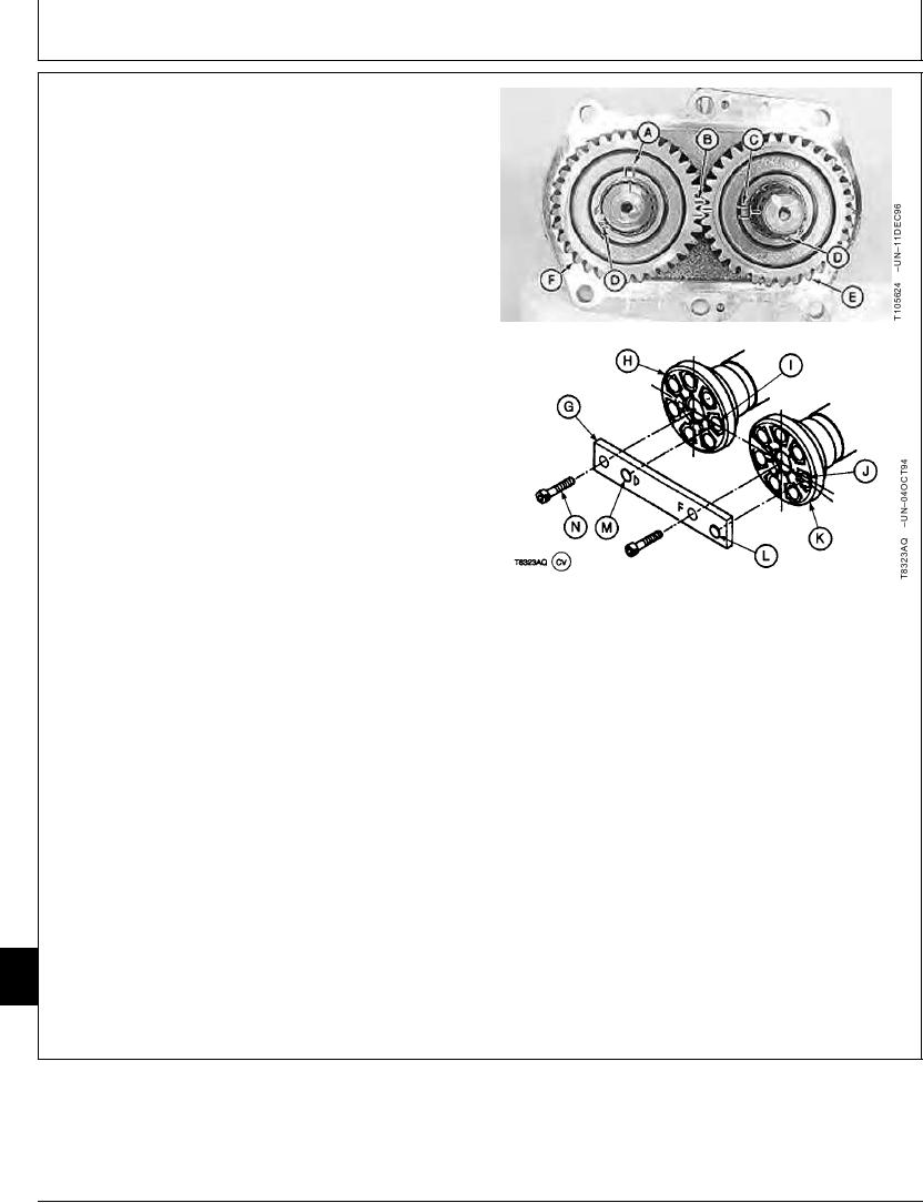
11. For original parts, install drive (E) and driven (F)
gears on shafts so timing marks (A, B, and C) are
aligned.
For new parts, install the JDG1054 Aligning Bar on
the socket (I and J) end of drive shafts.
Install aligning bar so end marked "Long Shaft Side"
is to the rear pump drive shaft (H). Turn shafts so
socket alignment dowels (L and M) engage a socket
in drive shafts. The socket for front pump drive shaft
is slightly below the centerline of socket for rear pump
drive shaft when shafts are timed correctly.
Install cap screws (N) to hold bar in position.
12. From the splined end of shafts, turn shafts to the left
to remove any play between socket alignment dowels
and sockets.
13. Install gear on the rear pump drive shaft. Install the
snap ring.
Install gear on front pump drive shaft. As necessary,
turn shaft slightly or turn gear to another position so
teeth on gears engage. Install snap ring.
A--Front Pump Drive Shaft-to-Driven Gear Timing
Mark
B--Driven Gear-to-Drive Gear Timing Mark
C--Rear Pump Drive Shaft-to-Drive Gear Timing
Mark
D--Snap Ring (2 used)
E--Drive Gear
F--Driven Gear
G--JDG1054 Aligning Bar (Pump Timing Tool)
H--Rear Pump Drive Shaft
I--Socket
J--Socket
K--Front Pump Drive Shaft
L--Socket Alignment Dowel
M--Socket Alignment Dowel
N--M8-1.25 Cap Screw (2 used)
33
3360
42
Continued on next page
TX,33,UU3784
1921SEP984/9
21-82