
TM 5-3805-280-24-2
Hydraulic System
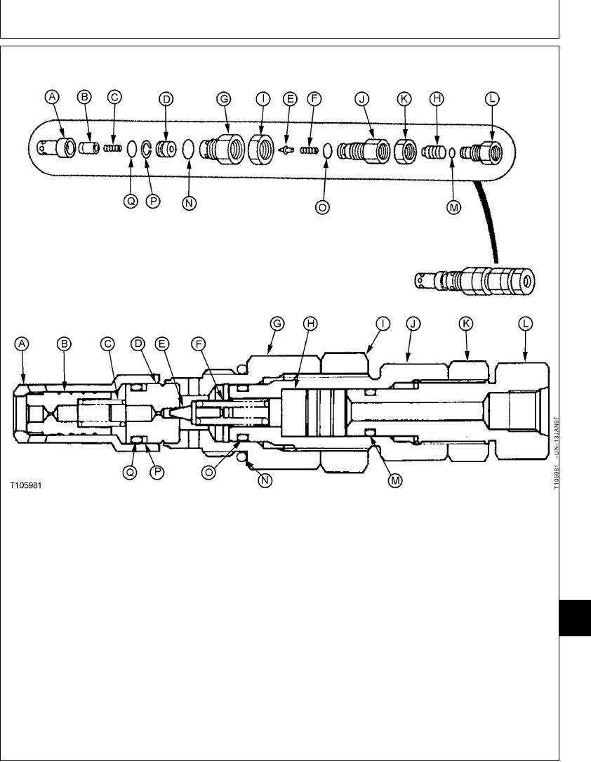
DISASSEMBLE AND ASSEMBLE SYSTEM RELIEF VALVE
A--Main Poppet Seat
F--Pilot Poppet Spring
K--27 mm Nut
P--Backup Ring
B--Main Poppet
G--Cartridge
L--First Adjusting Plug
Q--O-Ring
C--Main Poppet Spring
H--Piston
M--O-Ring
D--Pilot Poppet Seat
I--32 mm Nut
N--O-Ring
E--Pilot Poppet
J--Second Adjusting Plug
O--O-Ring
System Relief Valve 32 mm Nut--Specification
1. Disassemble valve for cleaning and inspection only.
Valve is serviced as an assembly.
Torque....................................................................... 83 Nm (61 lb-ft)
33
2. Tighten 27 mm nut (K).
3360
Tighten valve cartridge (G) into housing.
113
System Relief Valve 27 mm Nut--Specification
System Relief Valve Cartridge-to-Housing--Specification
Torque....................................................................... 64 Nm (47 lb-ft)
Torque....................................................................... 83 Nm (61 lb-ft)
Tighten 32 mm nut (I).
Continued on next page
TX,33,UU3802
1921SEP981/2
21-145