
TM 5-3805-280-24-2
Hydraulic System
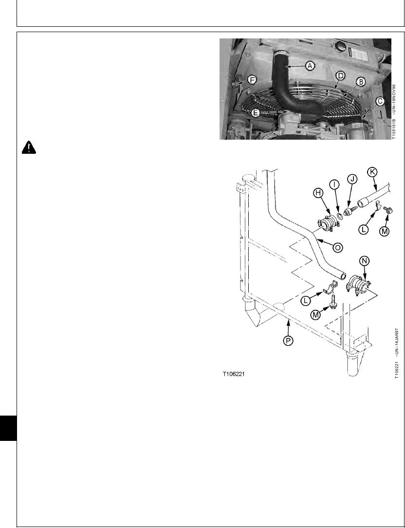
3. Remove parts (A--E).
4. Pull a vacuum in hydraulic oil tank using a vacuum
pump or drain hydraulic oil tank. Approximate oil
capacity is 148 L (39 gal).
5. Remove cover under the radiator and oil cooler.
6. For machines with air conditioning, remove cap screws
and lay the condenser on the battery cover.
CAUTION: The approximate weight of radiator
and oil cooler is 65 kg (140 lb).
Radiator and Oil Cooler--Specification
Weight.............................................................. 65 kg (140 lb) approximate
7. Connect a hoist to lifting eyes on radiator.
8. Disconnect upper radiator hose (A).
Remove fan guard (B), fan (D) and fan spacer (E).
Remove cap screws from radiator braces (F).
9. Disconnect lower radiator hose (C).
Remove cap screws (M) and clamps (L).
Loosen nuts on couplings (H and N). Slide couplings
onto the lines (K and O). Install cap and plugs.
A--Upper Radiator Hose
B--Fan Guard
33
C--Lower Radiator Hose
3360
D--Fan
136
E--Fan Spacer
F--Radiator Braces (2 used)
G--Frame-to-Radiator Bracket Cap Screw (4 used)
H--Coupling
I--Snap Ring
J--Swing Motor Make-Up Oil Restriction Valve
K--Oil Cooler-to-Hydraulic Oil Tank Return Line
L--Clamp (2 used)
M--Cap Screw and Lock Washer (2 used)
N--Coupling
O--Control Valve-to-Oil Cooler Line
P--Oil Cooler
Continued on next page
TX,33,UU3809
1921SEP983/6
21-168