
TM 5-3805-280-24-2
Rock Drill
44
9506
45
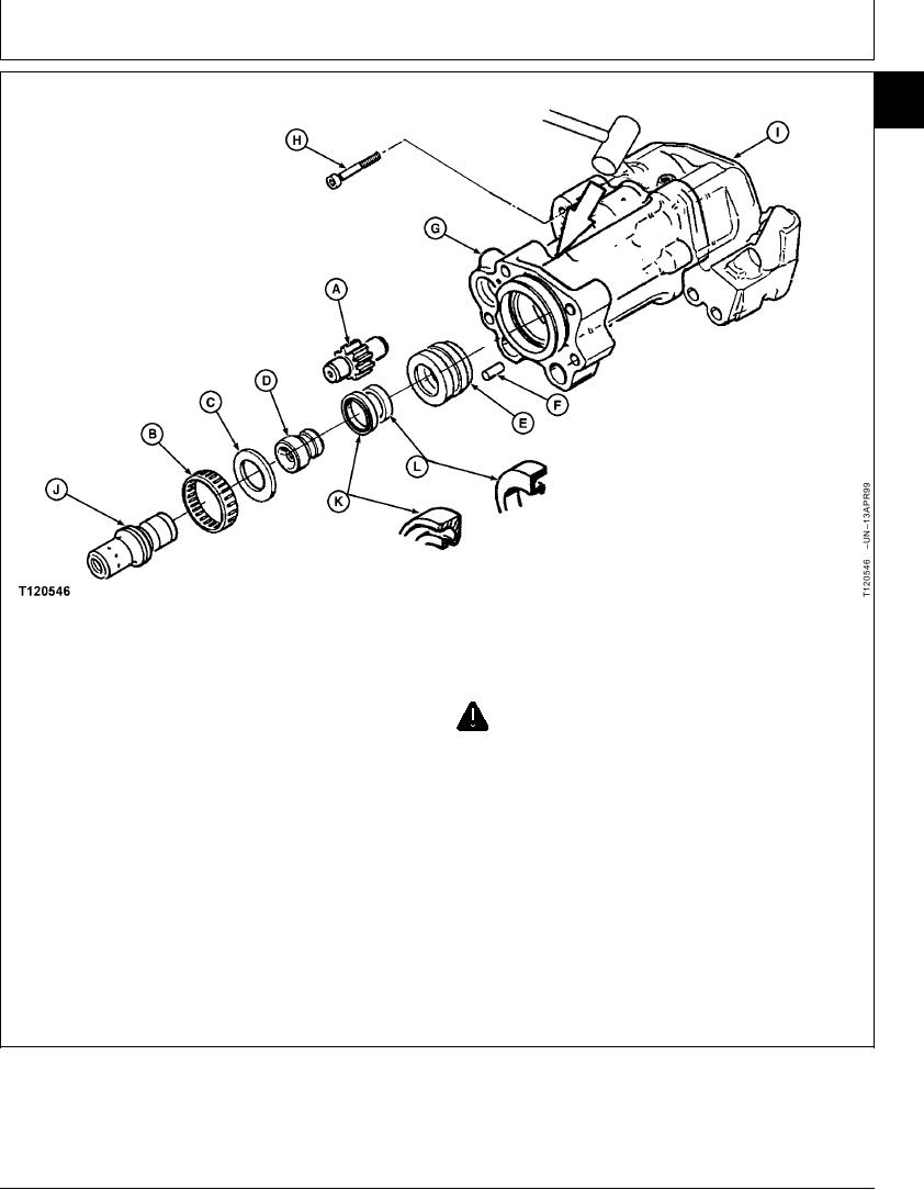
A--Gear
D--Shank Stop
G--Thrust Housing
J--Hydraulic Stop Piston
B--Needle Bearing
E--Guide
H--Screw (2 used)
K--Centering Part
C--Bronze Ring
F--Pin
I--Motor Body
L--Centering Part
34. Remove gear (A).
CAUTION: Ensure hydraulic stop piston is in
position before separating thrust housing
35. Remove needle bearing (B), bronze ring (C),
from hydraulic stop body. This will prevent
shank stop (D), and guide (E).
the hydraulic stop body from falling when
extracted.
36. Remove centering parts (K and L) from shank stop
(D).
39. Using dismounting-mounting tools, 77796 separate
thrust housing (G) from motor body (I).
37. Remove pin (F).
40. Remove thrust housing (G).
38. Remove two screws (H ).
Continued on next page
CED,OUOE019,5 1909MAR9917/20
23-42