
TM 5-3805-280-24-2
Rock Drill
44
9506
59
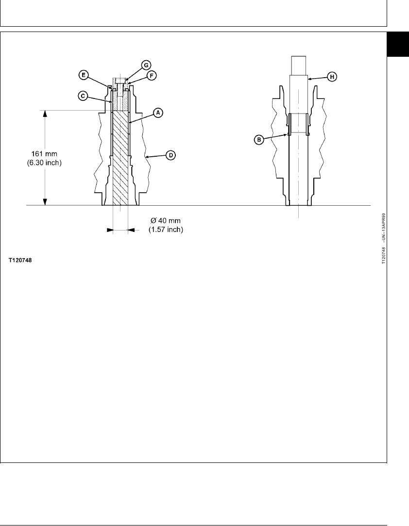
A--Guiding Ring (3 used)
D--Motor Body
F--Centering Ring
H--Bronze Ring Driving
B--Snap Ring
E--Segment Assembly (2
G--Socket Head Screw
Tool
C--Threaded Ring
used)
40. Extract worn guiding ring (A) approximately 0.28
35. Inspect opening of guiding ring (A). Replace if
inch using an hydraulic press.
opening is above 1.57 inches.
41. Replace two segment assemblies, 77795 (E) with
36. If required replace guiding ring (A) as follows:
segment assembly 60492.
37. Remove snap ring (B) with a screwdriver.
42. Remove guiding rings (A).
38. Install threaded ring, 60485 (C), two segment
43. Install new guiding rings (A) using bronze ring
assemblies, 77795 (E), centering ring, 60480 (F),
driving tool, 60483 (H) with an hydraulic press.
and socket head screw, 8861 (G) in the motor
body (D).
44. Install a new snap ring (B).
39. Secure all parts together by tightening socket
head screw, 8861 (G).
Continued on next page
CED,OUOE019,9 1912MAR999/34
23-55