
TM 5-3805-281-10
Maintenance--Every 2000 Hours
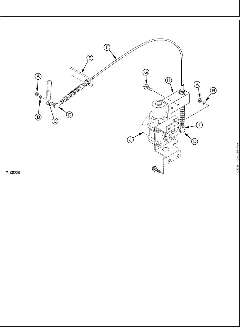
ENGINE SPEED CONTROL CABLE ADJUSTMENT
A--Nut (2 used)
D--Ball Joint (2 used)
G--Cap Screw and Lock
I--Engine Control Motor
B--Lock Washer (2 used)
E--Bracket
Washer (6 used)
Arm
C--Injection Pump Lever
F--Speed Control Cable
H--Bracket
J--Engine Control Motor
cable are centered in brackets. As needed, adjust
IMPORTANT: The ball joints (D) are installed on
cable in brackets to connect ball joint to lever or
the cable to full thread engagement.
arm.
A ball joint can be used to lengthen
a cable end, if needed, but must
3. Connect ball joint to the outer hole of engine control
have at least 6 mm (1/4 in.) of thread
motor arm (I).
engagement to avoid stripping the
threads on cable end.
4. Do Engine Control Motor Adjustment and then the
Engine Speed Learning Procedure. (See
1. Install ball joints (D) to full thread engagement.
procedures in this chapter.)
Tighten nuts.
2. Install speed control cable (F) in brackets (E and
H). Initially, tighten nuts so threaded portions of
CED,TX14740,6096
1920APR981/1