
TM 5-3805-281-24-1
Group 20
Adjustments
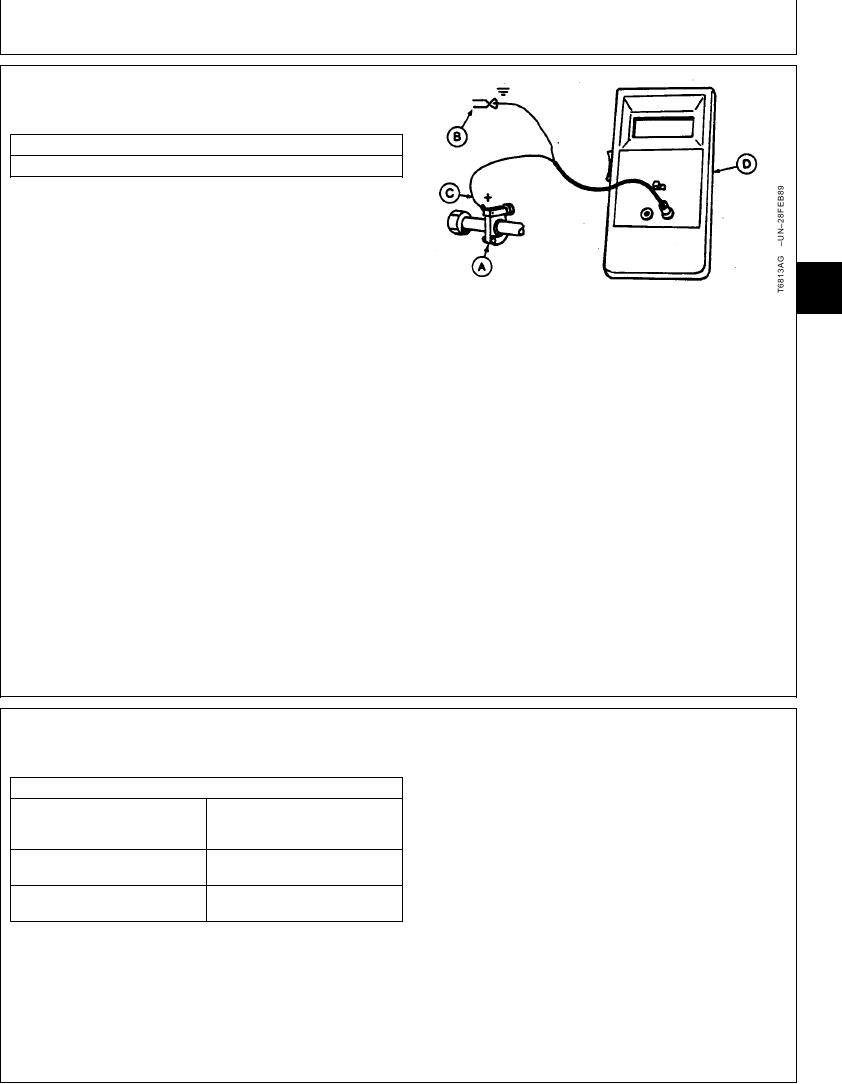
JT05801 CLAMP-ON ELECTRONIC
TACHOMETER INSTALLATION
SERVICE EQUIPMENT AND TOOLS
JT05801 Clamp-On Electronic Tachometer
1. Before installing clamp-on electronic tachometer,
remove the paint from a straight section of injection
line within 100 mm (4 in.) of No. 1 injection nozzle.
Use emery cloth to remove the paint.
9010
20
2. Install the clamp-on transducer (A). Tighten finger tight
1
only--DO NOT overtighten.
A--Clamp-On Transducer
B--Black Clip (-)
3. Connect the red clip (+) (C) to the clamp-on
C--Red Clip (+)
transducer.
D--Digital Readout Unit
4. Connect the black clip (-) (B) to a ground connection
such as the head of a cap screw or other metal part on
engine.
5. Start the engine. Check for a reading on the digital
readout unit (D).
CED,TX08227,2879
1911NOV971/1
FUEL SHUT-OFF SOLENOID LINKAGE
CHECK AND ADJUSTMENT
SPECIFICATIONS
Fuel Shut-Off Solenoid Ball Joint
3--6 mm (1/8--1/4 in.) short of
Hole-to-Fuel Shut-Off Lever Hole
alignment.
Distance
Fuel Shut-Off Solenoid
8 Nm (70 lb-in.)
Plunger-to-Ball Joint Nut Torque
Fuel Shut-Off Lever-to-Stop
within 3 mm (0.125 in.) of stop
Position Stop Distance
position stop
Continued on next page
TX,05,GG2305 1908JUN981/3