
TM 5-3805-281-24-1
Sub-System Diagnostics
ENGINE MODE AND RPM CONTROL UNIT (A4)
WORK MODE SELECTION SWITCH (S7)
ECONOMY (E) MODE SWITCH (S11)
The work mode selection switch selects the machine
operating modes (dig, grading, precision, or
When the economy (E) mode switch is pressed, a
attachment). Each time the switch is pressed the mode
ground is applied from engine mode and RPM control
selection is stepped to the next mode and the
unit pin 2 to monitor controller pin 35, causing the
corresponding mode indicator (H1, H2, H3 or H4) is
economy mode to be selected. With the economy
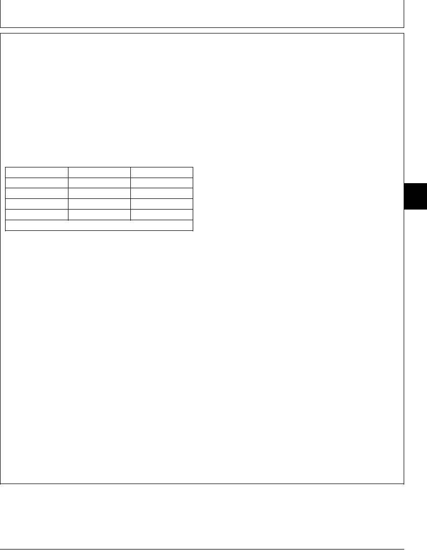
illuminated. The monitor controller provides different
mode selected, the monitor controller illuminates the
combinations of ground switched outputs to the engine
economy mode indicator light (H6), and provides a
and pump controller depending on the mode selected.
ground from pin 15 to engine and pump controller pin
The outputs are applied from mode 1 and mode 2
D5. Ground for the mode switch is applied to engine
monitor controller pins 21 and 22 to engine controller
mode and RPM control unit pin 1.
pins D3 and D4.
Pin 21a
Pin 22a
Mode
HIGH POWER (HP) MODE SWITCH (S12)
Dig
H
H
9015
When the high power (HP) mode switch is pressed, a
Grading
L
H
15
ground is applied from engine mode and RPM control
49
Precision
H
L
unit pin 4 to monitor controller pin 34, causing the high
Attachment
L
L
power mode to be selected. With the high power mode
H=5 0.5 volts; L=less than 1.0 volt.
a
selected, the monitor controller illuminates the high
power mode indicator light (H5), and provides a
PROPEL SPEED CHANGE SWITCH (S8)
ground from pin 23 to engine and pump controller pin
B11. Ground for the mode switch is applied to engine
The propel speed change switch selects slow or fast
mode and RPM control unit pin 3.
operating speed. When fast speed is selected, the
switch applies a ground from monitor controller pin 17
ENGINE RPM DIAL (R10)
to engine and pump controller pin B12.
The engine RPM dial provides a variable voltage to
AUTO IDLE (A/I) SWITCH (S13)
engine and pump controller pin D21 from engine mode
and RPM control unit pin 6 based on the setting of the
When the auto idle (A/I) switch is pressed, the A/I
RPM dial. Power for the RPM dial is applied across
indicator illuminates and the monitor controller applies
engine mode and RPM control unit pins 5 and 7.
a ground from monitor controller pin 13 to engine
motor and pump controller pin D6.
CED,OUOE012,27 1926JAN993/3
4-117