
TM 5-3805-281-24-1
Sub-System Diagnostics
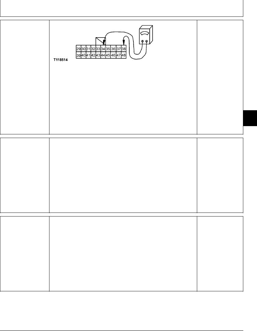
HIGH POWER (HP)
YES: Indicator lamp or
MODE SWITCH (S12)
controller has failed.
HARNESS CHECK
Replace.
NO: Harness has failed.
Repair.
T118514 UN21NOV98
Turn key switch OFF.
Disconnect 20-pin harness connector from monitor controller and display.
Connect ohmmeter between pins 34 and 38 of harness connector.
Measure continuity with high power (HP) mode switch in OFF and ON positions.
Does ohmmeter read open with switch in OFF position, and continuity with switch in
9015
ON position?
15
55
1/1
Turn key switch ON.
YES: Switch and
WORK MODE
indicators are OK.
SELECTION SWITCH
Push WORK MODE switch several times to cycle through all work mode selections
(S7), DIG MODE
(dig, grading precision, attachments).
NO: If modes do not
INDICATOR LIGHT (H1),
change, switch or monitor
GRADING MODE
controller has failed.
Does mode selection change when switch is pressed?
INDICATOR LIGHT (H2),
Repair or replace.
PRECISION MODE
Does each mode indicator come ON as mode is selected?
INDICATOR LIGHT (H3)
Replace indicator lamp
AND ATTACHMENT
that does not come ON.
MODE INDICATOR LIGHT
(H4) CHECK
1/1
Turn key switch ON.
AUTO IDLE SWITCH
YES: Switch and indicator
(S13) AND AUTO IDLE
are OK.
MODE INDICATOR LIGHT
Push auto idle (A/I) switch.
(H7) CHECK
NO: Check indicator
Does auto idle (A/I) indicator come ON?
lamp. If lamp is OK,
switch or controller has
failed. Replace.
Push auto idle (A/I) again.
Does auto idle (A/I) indicator go OFF?
1/1
4-123