
TM 5-3805-281-24-1
Sub-System Diagnostics
1 MONITOR CONTROLLER AND DISPLAY CIRCUIT DIAGNOSTIC PROCEDURES
IMPORTANT: Do not disconnect electrical connectors while the engine is running. Damage to Engine and
Pump Controller or other components may result. Disconnect connectors only when instructed during a
test or check.
NOTE: Before troubleshooting the circuits, clean all pins in the monitor controller and harness connectors using a
non-conductive lubricating contact cleaner, then try the circuit operation again before proceeding. TY16324 Contact
Cleaner can be used.
1/1
Remove fuse block cover.
MONITOR CONTROLLER
YES: Fuse is OK.
AND DISPLAY 5 AMP
9015
FUSE (F6) CHECK
Remove fuse from fuse block.
NO: Replace Fuse. If
15
fuse blows again, check
51
Using ohmmeter, check fuse for continuity.
for short.
Is continuity measured?
1/1
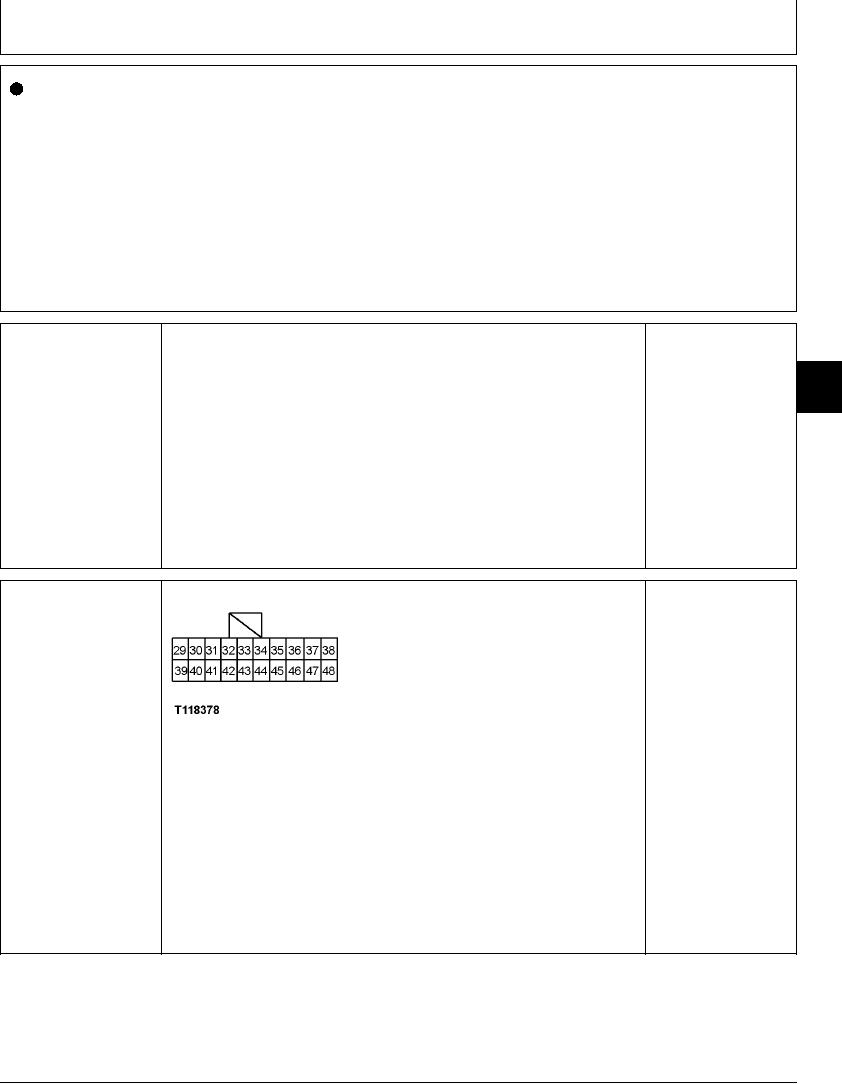
MONITOR CONTROLLER
YES: Go to next check.
AND DISPLAY (A5)
HARNESS POWER
NO: Repair harness.
CHECK
T118378 UN21NOV98
Turn key switch OFF.
Disconnect 20-pin harness connector from monitor controller and display.
Measure voltage on pins 30, 39 and 40 of harness connector.
Is 24 volts measured?
1/1