
TM 5-3805-281-24-1
Hydraulic System
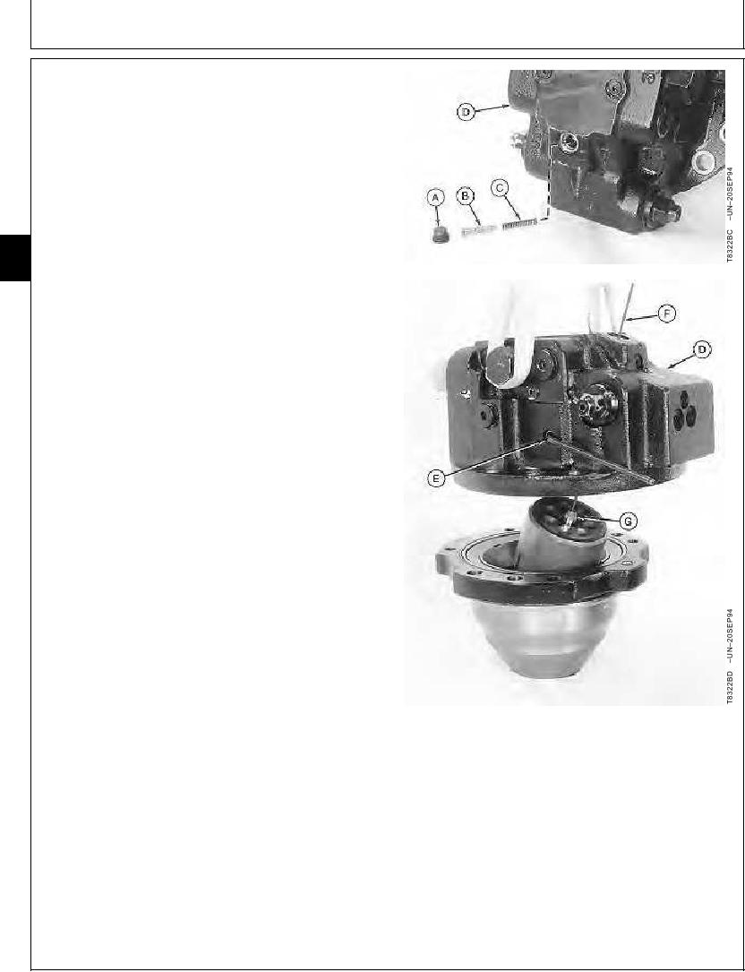
35. Remove parts (A--C) from motor valve housing (D).
36. Remove plug and O-ring from port (E) on side of
valve housing.
37. Move valve plate and servo piston to align pivot plug
with port. Install a 6 mm Allen wrench in pivot plug to
hold valve plate and link in position.
38. Install a 4.8 mm (3/16 in.) wooden dowel or soft rod
(F) through reducing valve port and center of valve
02
0260
plate.
24
39. Lift motor valve housing into position over motor shaft
and brake housing. Align housings and put dowel into
bore of center shaft (G). Carefully bring the housings
together.
40. Install and tighten four housing cap screws.
Brake Valve-to-Motor Housing Cap Screw--Specification
Torque ......................................................................... 217 Nm (160 lb-ft)
41. Remove dowel and install parts (A--C). Tighten plug.
Brake Pressure Reducing Spool Plug--Specification
Torque ............................................................................. 34 Nm (25 lb-ft)
42. Remove Allen wrench. Install and tighten plug and
O-ring.
Alignment Port Plug--Specification
Torque ............................................................................. 88 Nm (65 lb-ft)
A--Plug and O-Ring
B--Pressure Reducing Spool
C--Spring
D--Motor Valve Housing
E--Alignment Port
F--Wooden Dowel or Rod
G--Center Shaft
CED,OUOE023,174 1901JUN9814/14
10-63