
TM 5-3805-281-24-2
Removal and Installation
6. If valve clearance needs to be adjusted, loosen the
locknut on rocker arm adjusting screw. Turn adjusting
screw until feeler gauge slips with a slight drag. Hold
the adjusting screw from turning with screwdriver and
tighten locknut.
Valve Adjusting Screw Locknut--Specification
Torque ............................................................................. 27 Nm (20 lb-ft)
Recheck clearance again after tightening locknut.
Readjust clearance as necessary.
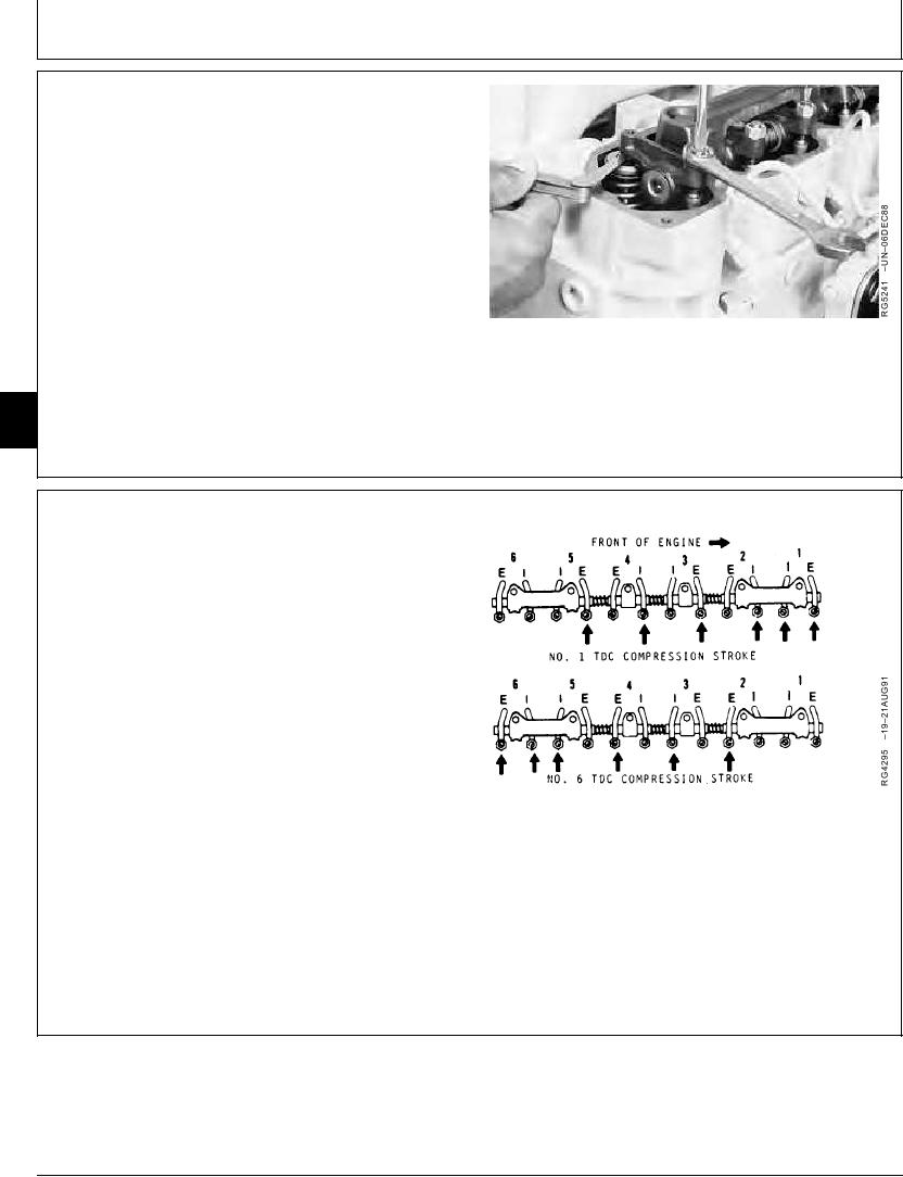
7. Rotate flywheel 360 until No. 6 piston is at "TDC" of
its compression stroke. Rocker arms for No. 6 piston
should be loose.
04
0400
38
TX,0400,DH5389 1918MAY983/4
8. Check and adjust (as needed) valve clearance to the
same specifications on Nos. 2, 4 and 6 exhaust and
Nos. 3, 5 and 6 intake valves. Tighten valve adjusting
screw locknut.
Intake Valve--Specification
Clearance .............................................. 0.331--0.431 mm (0.013--0.017
in.)
Exhaust Valve--Specification
Clearance .............................................. 0.661--0.761 mm (0.026--0.030
in.)
Valve Adjusting Screw Locknut--Specification
Torque ............................................................................. 27 Nm (20 lb-ft)
9. Recheck clearance on all valves again after locknut is
tightened.
TX,0400,DH5389 1918MAY984/4
11-38