
TM 5-3805-281-24-2
Removal and Installation
IMPORTANT: Visually inspect contact surfaces of
valve tips and rocker arm wear pads.
Check all parts for excessive wear,
breakage, or cracks. Replace parts that
show visible damage.
Rocker arms that exhibit excessive
valve clearance should be inspected
more thoroughly to identify damaged
parts.
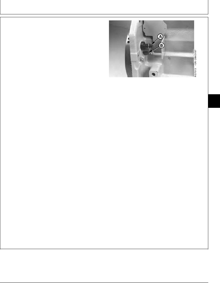
2. Remove plastic plugs from cylinder block bores and
install JDE81-1 or JDG820 Flywheel Turning Tool (A)
and JDE-81-4 Timing Pin (B).
A--Flywheel Turning Tool
B--Timing Pin
3. Rotate the engine with the flywheel turning tool until
04
timing pin engages timing hole in flywheel.
0400
37
4. If the rocker arms for the No. 1 cylinder are loose, the
engine is at No. 1 "TDC" Compression.
If the rocker arms for the No. 6 cylinder are loose, the
engine is at No. 6 "TDC" Compression. Rotate the
engine one full revolution to No. 1 "TDC" Compression.
5. With the engine lock-pinned at "TDC" of No. 1 piston's
compression stroke, check and adjust (as needed)
valve clearance on Nos. 1,3 and 5 exhaust valves and
Nos. 1, 2 and 4 intake valves.
Intake Valve--Specification
Clearance .............................................. 0.331--0.431 mm (0.013--0.017
in.)
Exhaust Valve--Specification
Clearance .............................................. 0.661--0.761 mm (0.026--0.030
in.)
Continued on next page
TX,0400,DH5389 1918MAY982/4
11-37