
TM 5-3805-281-24-2
Crankshaft, Main Bearings, and Flywheel
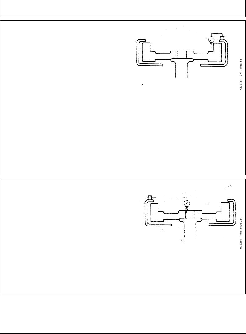
CHECK FLYWHEEL FACE FLATNESS
1. Mount dial indicator base on flywheel housing. Position
pointer to contact driving ring mounting surface. Do not
allow pointer to contact driving ring mounting holes.
IMPORTANT: Maintain constant end pressure on
crankshaft to hold shaft against thrust
bearing when measuring flywheel face
runout.
2. Rotate flywheel by turning crankshaft. Read total dial
indicator movement. Resurface flywheel face or
replace as required.
Flywheel Face--Specification
Flatness ...................................................... 0.23 mm (0.009 in.) maximum
variation
Flatness .................................................. 0.013 mm (0.0005 in.) maximum
variation per 25 mm (1.0 in.) of
travel
RG,RG34710,1160
1923OCT971/1
CHECK PILOT BEARING BORE
CONCENTRICITY
1. Mount dial indicator on flywheel housing face and
position pointer to contact I.D. of pilot bearing bore in
flywheel.
2. Rotate flywheel by turning crankshaft. Read total dial
indicator movement.
Flywheel Pilot Bearing--Specification
Bore Concentricity .................................... 0.127 mm (0.005 in.) maximum
Checking Flywheel Pilot Bearing Bore
variation
RG,RG34710,1161
1923OCT971/1