TM 5-3805-281-24-2
Cooling System
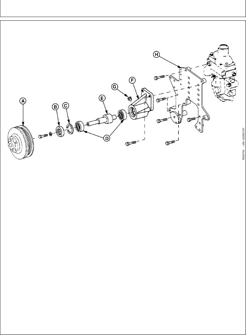
REPLACE BEARINGS IN HEAVY-DUTY, ADJUSTABLE FAN DRIVE ASSEMBLY
Heavy-Duty Adjustable Fan Drive Assembly
A--Fan Hub/Pulley
C--Snap Ring
E--Shaft
G--Pipe Plug
B--Grease Seal
D--Ball Bearing (2 Used)
F--Bearing Housing
H--Support Plate
Measure parts and compare with specifications
TO DISASSEMBLE FAN DRIVE:
given below.
1. Remove belts and remove fan. Remove fan drive
Adjustable Fan Drive Housing--Specification
assembly from engine.
ID ........................................................................ 71.999--72.025 mm
2. Clamp fan hub/pulley (A) in a soft-jawed vise.
(2.8346--2.8356 in.)
Support fan hub (so it does not fall to floor), and
remove cap screw securing hub to shaft (E).
Adjustable Fan Drive Shaft--Specification
Remove fan hub.
OD....................................................................... 35.001--35.017 mm
(1.3780--1.3786 in.)
3. Remove pipe plug (G), grease seal (B), and snap
ring (C). Discard seal and snap ring.
Adjustable Fan Drive Bearing--Specification
4. Remove shaft with bearings (D) by lightly tapping
ID ........................................................................ 34.987--35.013 mm
with a rubber mallet or brass hammer.
(1.3774--1.3785 in.)
OD....................................................................... 71.987--72.013 mm
(2.8341--2.8351 in.)
5. Remove bearings from shaft using a press and
discard bearings.
6. Thoroughly clean and inspect shaft and bearing
housing (F) for cracks or any other damage.
Continued on next page
RG,RG34710,1239
1923OCT971/4

