
TM 5-3805-281-24-2
Cooling System
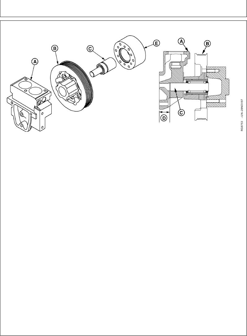
REPLACE BEARINGS IN WATER MANIFOLD-MOUNTED, FIXED FAN DRIVE ASSEMBLY
Fixed Fan Drive Assembly
A--Water Manifold
D--Bearing Shaft Installed
B--Fan Pulley
Dimension
E--Fan Spacer Hub1
C--Bearing Shaft
outer race to prevent damage to the
TO DISASSEMBLE FAN DRIVE:
bearing.
1. Remove three water manifold-to-cylinder head cap
5. Install new bearing into pulley until outer race
screws. Remove water manifold (A) and fan pulley
bottoms in bore of pulley. End of shaft will extend
(B) assembly from cylinder head and lift to dislodge
through bearing stop.
water bypass pipe from manifold.
Fixed Fan Drive Shaft--Specification
2. Support front face of water manifold and use a
press to push bearing (C) and pulley out of
OD....................................................................... 25.387--25.400 mm
manifold.
(0.9995--1.0000 in.)
3. Support front face of fan pulley and push bearing
Fixed Fan Drive Bearing--Specification
out of pulley, and fan spacer (if equipped). Discard
OD....................................................................... 47.612--47.625 mm
bearing.
(1.8745--1.8750 in.)
4. Thoroughly inspect water manifold and pulley for
Fixed Fan Drive Pulley (Bearing End)--Specification
cracks or damage. Measure parts and compare
readings with specifications shown. Replace parts
ID ........................................................................ 47.576--47.612 mm
as necessary.
(1.8731--1.8745 in.)
IMPORTANT: Support fan pulley on a flat, firm
surface and press only on bearing
1
In some applications, bearing is pressed into hub (E). The fan
spacer and pulley are then bolted to hub. In some applications, the
fan spacer is press-fit into the pulley. Dimension (D) is the same for
all applications.
Continued on next page
RG,RG34710,1240
1923OCT971/2