
TM 5-3805-281-24-2
Electrical System and Electrical Engine Controls
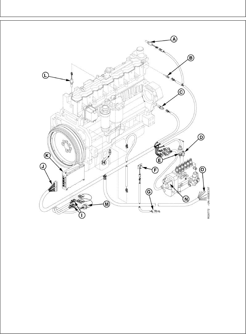
ELECTRONIC ENGINE CONTROL SYSTEM AND SENSORS (DEERE ECU SHOWN)
Electronic Engine Control System and Sensors (John Deere ECU Shown)
A--Manifold Air
E--Fuel Temperature
I--Diagnostic and Service
N--Rack Actuator
Temperature (MAT)
Sensor
Connectors
Assembly
O--Taped Wires1
Switch
F--Transient Voltage
J--Electronic Wiring
B--Engine Coolant
Protection (TVP)
Harness
Temperature Sensor
Module
K--Engine Control Unit
C--Auxiliary Engine Speed
G--Fuse
(ECU)
Sensor
H--Engine Oil Pressure
L--Loss of Coolant Sensor
D--Fuel Shutoff Solenoid
Sensor
M--CAN Bus Connector
following manuals: Earlier Bosch ECU
IMPORTANT: DO NOT pressure wash the Engine
systems--CTM68. Later John Deere ECU
Control Unit (ECU).
systems--CTM134.
NOTE: For diagnosis and testing of the electronic
engine control and sensors, refer to the
1
These wires do not have terminal ends attached. They are to be
spliced and used per application requirements.
RG,RG34710,1324
1923OCT971/1