
TM 5-3805-281-24-2
Cooling System
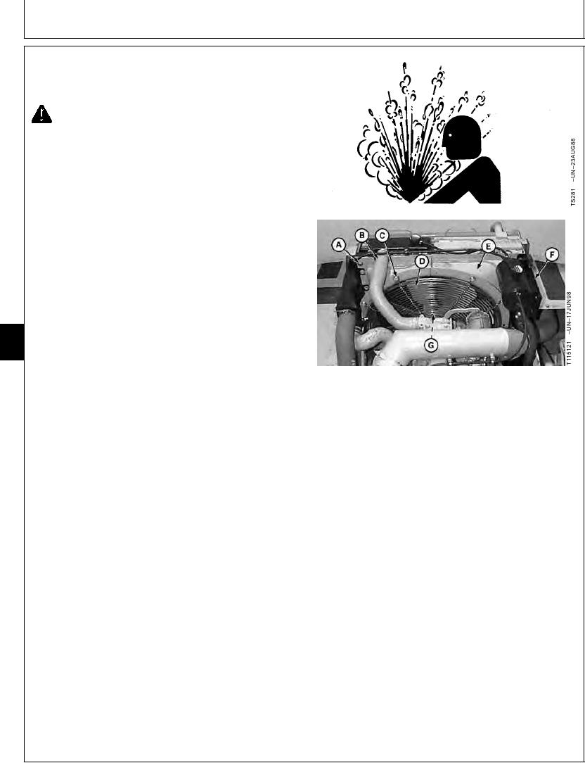
REMOVE AND INSTALL FAN, SHROUD, AND
GUARDS
CAUTION: Explosive release of fluids from
pressurized cooling system can cause serious
burns.
Shut off engine. Only remove filler cap when
cool enough to touch with bare hands. Slowly
loosen cap to first stop to relieve pressure
before removing completely.
1. Drain engine coolant until coolant level is below upper
radiator hose (B).
2. Remove radiator expansion tank. (See procedure in
this group.)
3. Loosen clamps. Remove upper radiator hose (B).
4. Remove cap screws (C). Remove fan guard (D).
05
0510
5. Remove cap screws (A). Move fan shroud (E) toward
2
engine.
A--Cap Screw (12 used)
6. Remove four cap screws. Remove fan, and spacer (G).
B--Upper Radiator Hose
C--Cap Screw (4 used)
7. Remove fan shroud (E).
D--Guard
E--Shroud
8. Replace parts as necessary.
F--Expansion Tank
G--Cap Screws, Fan, and Spacer
9. Install fan shroud (E). Move shroud towards engine.
10. Install fan and spacer. Tighten cap screws.
Fan-to-Pulley Cap Screw--Specification
Torque ............................................................................. 47 Nm (35 lb-ft)
11. Install fan shroud (E). Tighten cap screws (A).
Fan Shroud-to-Radiator Cap Screw--Specification
Torque ............................................................................. 73 Nm (54 lb-ft)
12. Install fan guard (D). Tighten cap screws (C).
Continued on next page
CED,OUOE024,215
1918MAY981/2