
TM 5-3805-281-24-2
Removal and Installation
CAUTION: To avoid injury from escaping fluid
under pressure, stop engine and relieve the
pressure in the system before disconnecting or
connecting hydraulic or other lines. Tighten all
connections before applying pressure.
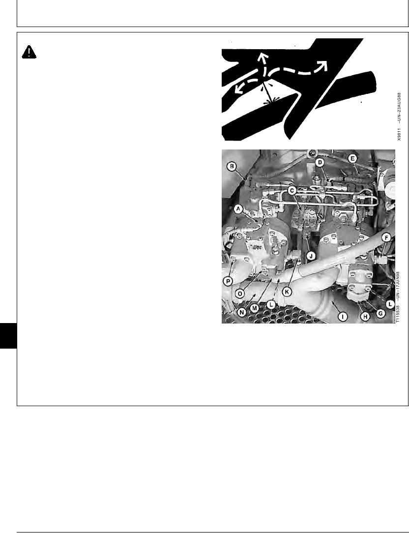
4. Disconnect lines (A--D, F, H, J, K, M and N).
5. Disconnect electrical connectors (E and L).
A--Rear Pump Regulator Front Piston
Port-to-Solenoid Valve Manifold
B--Rear Pump Regulator Rear Piston Port-to-PC
Sensor Block Line
C--Pilot Pump Top Port-to-Pilot Filter Line
D--Front Pump Regulator Rear Piston Port-to-PC
Sensor Block Line
E--Engine Speed Sensor Electrical Connector
F--Front Pump Side Port-to-Plugged End on Frame
G--Cap Screw (4 used)
H--Front Pump Pressure Port-to-Front Control Valve
Port D Line
I--Clamp (4 used)
J--Pilot Pump Bottom Port-to Reservoir Line
K--Rear Pump Side Port-to-Plugged End on Frame
08
L--Front and Rear Pump Pressure Sensor Electrical
0800
Connectors
2
M--Rear Pump Pressure Port-to-Rear Control Valve
Pressure Port Line
N--Reservoir-to-Front and Rear Pumps Suction Line
O--Cap Screw (4 used)
P--Cap Screw (8 used)
Continued on next page
CED,OUOE024,231
1922MAY982/3
14-2