
TM 5-3805-281-24-2
Elements
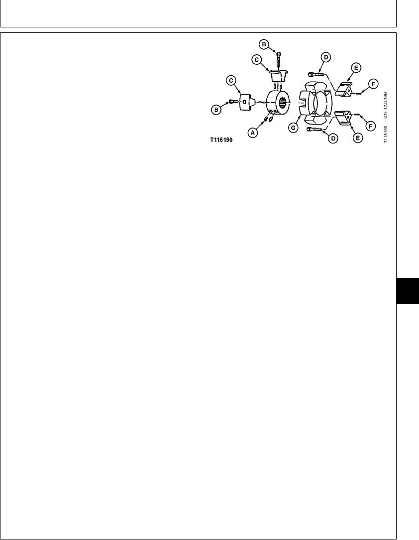
NOTE: Flex coupling may come off with pump or stay on
the flywheel.
7. Remove parts (A--G).
8. Replace parts as necessary.
9. Install parts (A--G). Apply thread lock and sealer
(medium strength) to set screws (A) and cap screws (B
and D).
10. Tighten set screws (A).
A--Set Screw
Set Screw-to-Coupling--Specification
B--Cap Screw
C--Insert
Torque ........................................................................... 108 Nm (80 lb-ft)
D--Cap Screw
E--Insert
11. Tighten cap screws (B and D).
F--Spring Pin
G--Coupling
Flywheel Insert and Hub Insert Cap Screw--Specification
Torque ......................................................................... 312 Nm (230 lb-ft)
12. Install splitter drive and hydraulic pump. (See
procedure in Group 0851.)
IMPORTANT: Hydraulic pump and drive gearbox will
be damaged if not filled with oil before
07
starting engine. Procedure must be
0752
performed whenever a new pump or
3
gearbox is installed or oil has been
drained from the pump, gearbox or
hydraulic oil tank.
13. Fill pump housing and pump drive gearbox with oil.
(See Hydraulic Pump and Drive Gearbox Start-Up
Procedure in Group 3360.)
Apply pipe sealant to drain plug threads.
14. Install muffler and muffler bracket. (See procedure in
Group 0530.)
15. Install hood, hood support, and cover.
TX,07,VV2579 1907JUL982/2
13-3