
TM 5-3805-281-24-2
Hydraulic System
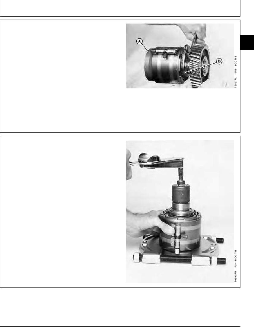
7. Apply clean hydraulic oil to threads of bearing nut (B).
Install nut.
33
3360
8. Install a ring compressor to align bearings on drive
41
shaft (A).
9. Tighten nut (B) until nut is tight against roller bearing.
Turn drive shaft back and forth several times to seat
the roller bearings.
A--Drive Shaft
B--Bearing Nut
CED,OUOE027,299 1904JUN985/14
10. Place drive shaft with attached parts on knife-edged
puller. Be sure ring compressor holds the weight of
the assembly.
11. Install DF1037 Hydraulic Pump Torque Adapter on
spline of drive shaft. Make a record of the starting
torque. Starting torque must be as specified. (See
Section 99 for instructions to make tool.)
Drive Shaft--Specification
Torque .......................................................... 2.5--3.5 Nm (22--30 lb-in.)
starting
Continued on next page
CED,OUOE027,299 1904JUN986/14
19-79