
TM 5-3805-281-24-2
Hydraulic System
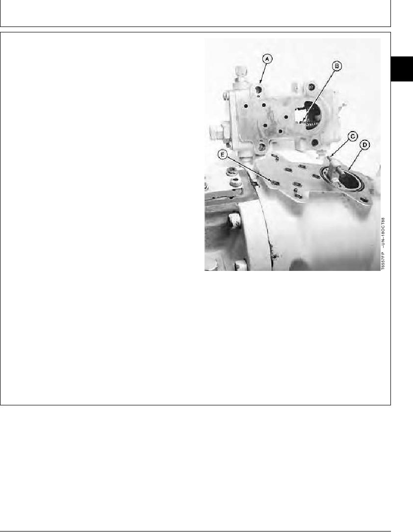
27. Install O-rings (E and D).
33
NOTE: Grooves (B) are shown out of assembly position
3360
for clarity of photograph.
45
28. Remove air bleed plugs from pump regulator (A).
Install regulator making sure groove (B) in remote
control sleeve and load sleeve engage dowel pin (C)
in feedback link. Check through hole that groove in
sleeves engage dowel pin.
29. Tighten cap screws.
Pump Regulator-to-Pump Housing Cap Screw--Specification
Torque ............................................................................. 49 Nm (36 lb-ft)
30. Install air bleed plug.
A--Pump Regulator
B--Grove
C--Dowel Pin
D--O-Ring
E--O-Ring (5 used)
Continued on next page
CED,OUOE027,299
1904JUN9813/14
19-83