
TM 5-3805-281-24-2
Hydraulic System
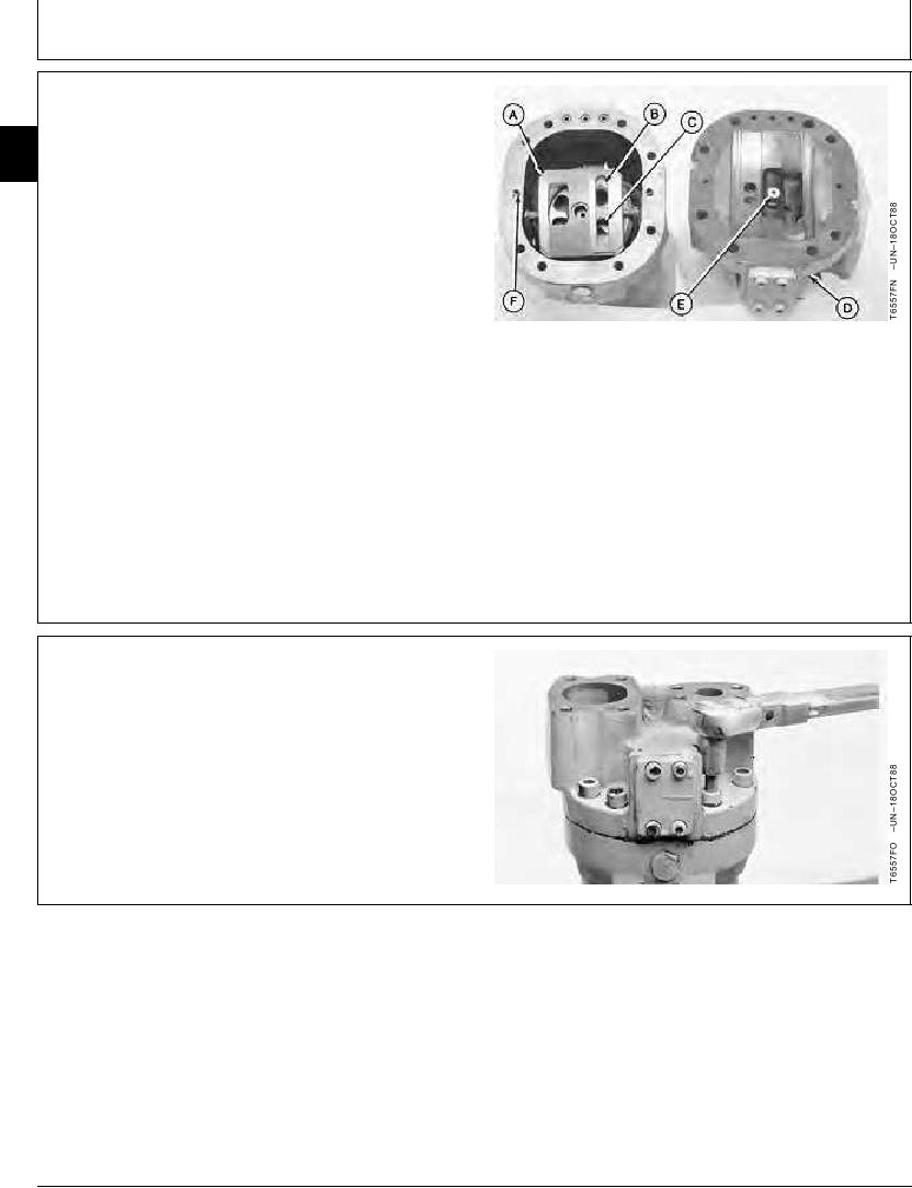
24. Position valve plate (A) and rotor (B) as shown. Be
sure outlet port (C) is positioned as shown.
33
3360
25. Install cylinder head (D), aligning pin (E) with center
44
shaft bore in valve plate (A) and holes with spring
pins (F).
A--Valve Plate
B--Rotor
C--Outlet Port
D--Cylinder Head
E--Pin
F--Spring Pin (2 used)
CED,OUOE027,299 1904JUN9811/14
26. Install washers and cap screws and tighten.
Cylinder Head-to-Pump Housing Cap Screw--Specification
Torque ........................................................................... 108 Nm (80 lb-ft)
Continued on next page
CED,OUOE027,299 1904JUN9812/14
19-82