
TM 5-3805-281-24-2
Hydraulic System
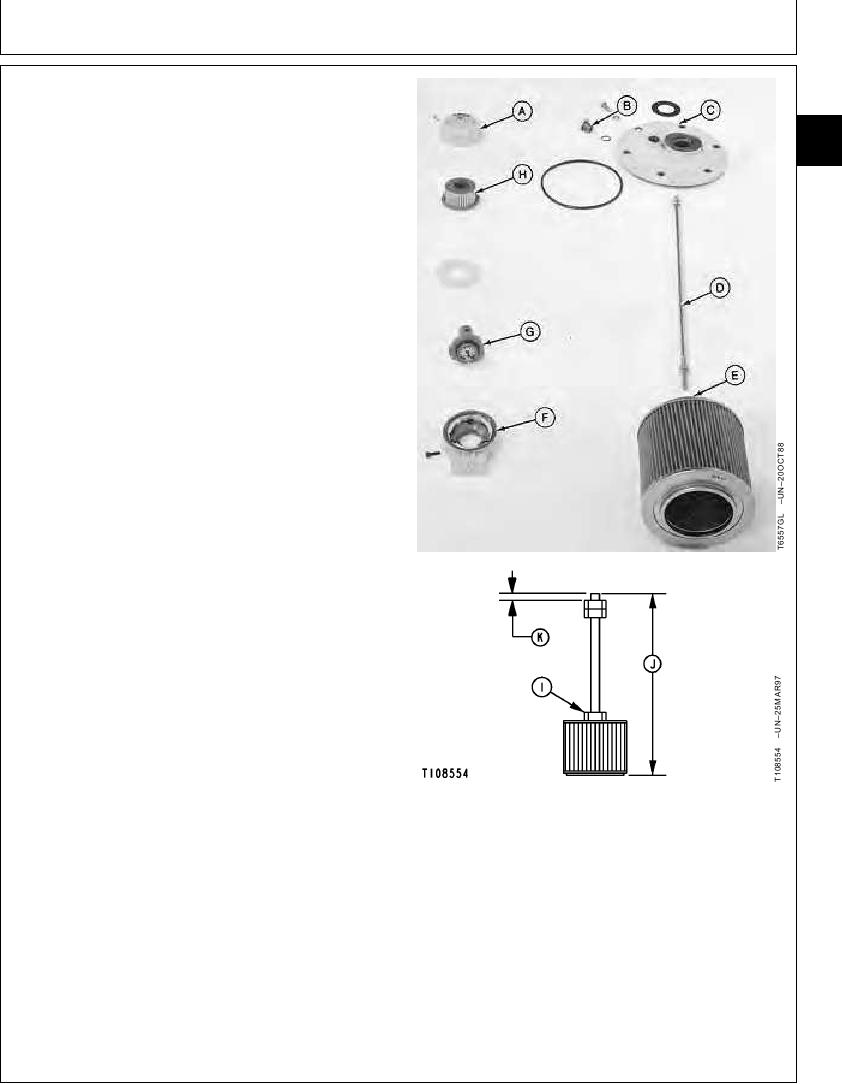
4. Remove parts (D--H).
33
Replace parts as necessary.
3360
135
IMPORTANT: To ensure suction strainer is held in
position on suction tube, the rod and
suction strainer must be adjusted to the
correct length.
5. Tighten nuts at top end of rod so top nut is 20 mm
(0.79 in.) from end of rod.
Adjust rod so the length from end of rod to the bottom
of suction strainer is to specification.
Tighten nut (I).
Rod-to-Suction Strainer Nut--Specification
Torque .......................................................................... 17 Nm (153 lb-in.)
Rod and Suction Strainer--Specification
Distance................................................. 20 mm (0.79 in.) from end of rod
to top nut
Length.................................................. 702 mm (27.6 in.) from end of rod
to bottom of suction strainer
6. Install suction strainer and rod (D and E) making sure
it is pushed down on suction tube at bottom of oil tank.
7. Install cover (C). Make sure rod is through hole in
cover.
Tighten cap screws.
Cover-to-Hydraulic Oil Tank Cap Screw--Specification
Torque ............................................................................. 49 Nm (36 lb-ft)
Install parts (A, B, and F--H).
8. Add hydraulic oil to tank until it is between marks on
A--Filler Cap
sight glass. (See Hydraulic Oil in Group 0004.)
B--Vent Plug
C--Cover
D--Rod and Nuts
E--Suction Strainer
F--Housing
G--Relief Valve
H--Filter
I--Nut
J--702 mm (27.6 in.)
K--20 mm (0.79 in.)
Continued on next page
CED,OUOE026,6
1918JUN982/3
19-163