
TM 5-3805-281-24-2
Hydraulic System
1--Cap Screw (6 used)
10--Cover
19--Lock Washer (4 used)
26--Snap Ring
2--O-Ring
11--O-Ring
20--Cap Screw (4 used)
27--Cap Screw
3--Plug
12--Nut (3 used)
21--Plug
28--Bracket
33
4--Filter
13--Rod
22--Cap Screw and Lock
29--Level Switch
3360
5--O-Ring
14--Suction Strainer
Washer (6 used)
30--Filter
131
6--Allen Screw (4 used)
15--Washer Seal
23--Suction Pipe
31--Valve
7--Housing
16--Cap Screw (2 used)
24--O-Ring
32--Spring
8--Packing
17--Gauge
25--Oil Cooler Bypass
33--O-Ring
9--Cap Screw (6 used)
18--Washer (4 used)
Valve
34--Cover
Rod and Suction Strainer--Specification
NOTE: It is not necessary to drain and remove the
hydraulic oil tank if only the return filter
Length .................................................. 702 mm (27.6 in.) from end of
element (30) is being removed. (See
rod to bottom of suction strainer
procedures in this group.)
Distance ................................................. 20 mm (0.79 in.) from end of
rod to top nut
1. Tighten cap screws (1, 9 and 22).
Tighten nut (12).
Cover-to-Oil Tank Cap Screw--Specification
Rod-to-Suction Strainer Nut--Specification
Torque....................................................................... 49 Nm (36 lb-ft)
Torque.................................................................... 17 Nm (153 lb-in.)
2. Adjust rod (13) so length from end of rod to bottom
of filter (screen) (14) is to specification. Tighten nuts
(12) at top end of rod so top nut is the specified
distance from end of rod.
CED,OUOE026,8
1918JUN982/2
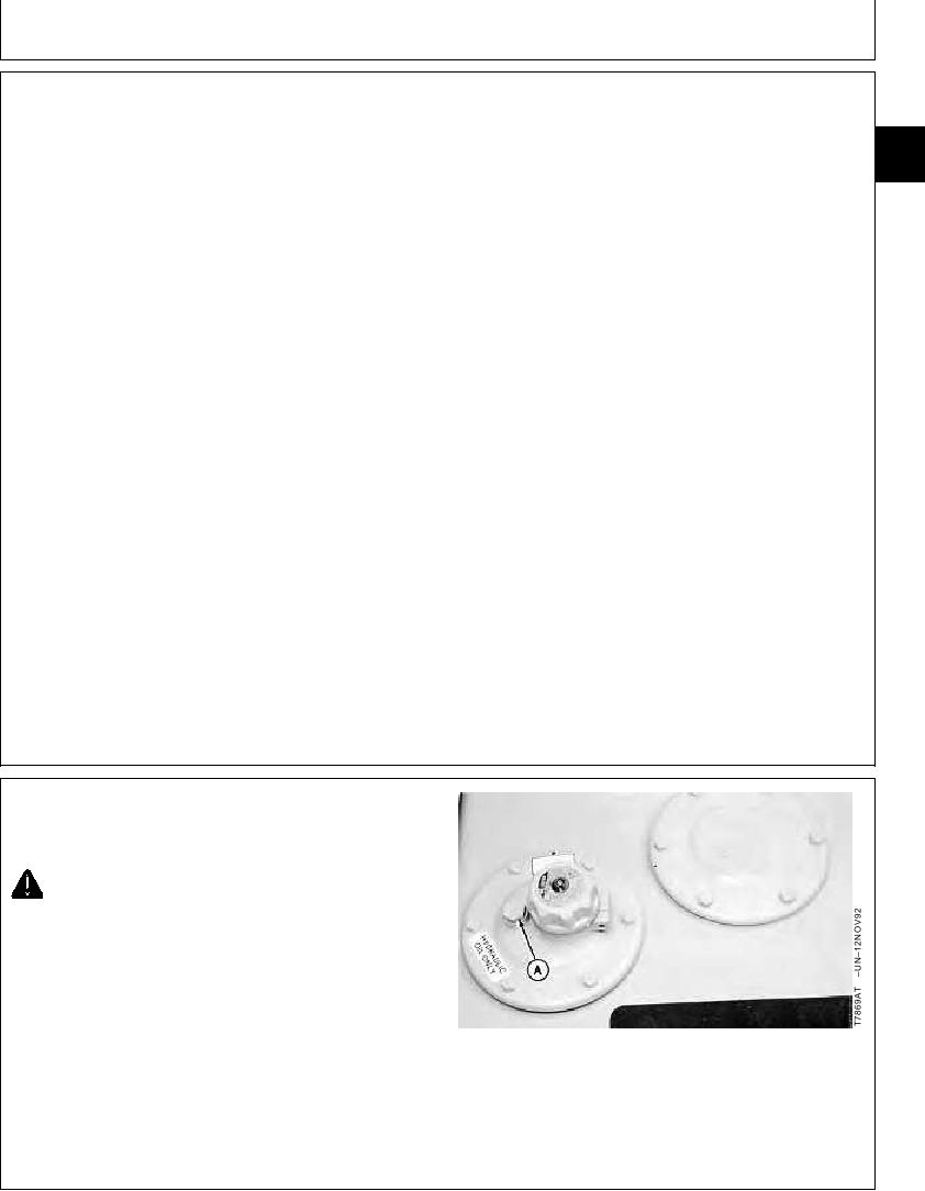
REMOVE AND INSTALL RETURN FILTER
AND BYPASS VALVE
CAUTION: The hydraulic oil tank is pressurized.
High pressure release of oil from pressurized
system can cause serious burns or penetrating
injury. Release pressure from tank by loosening
vent plug. It is not necessary to remove vent
plug.
1. Loosen vent plug (A) to release air pressure from
hydraulic oil tank.
A--Vent Plug
Continued on next page
CED,OUOE026,7
1918JUN981/3