
TM 5-3805-281-24-2
Mechanical Drive Elements
43
4350
28
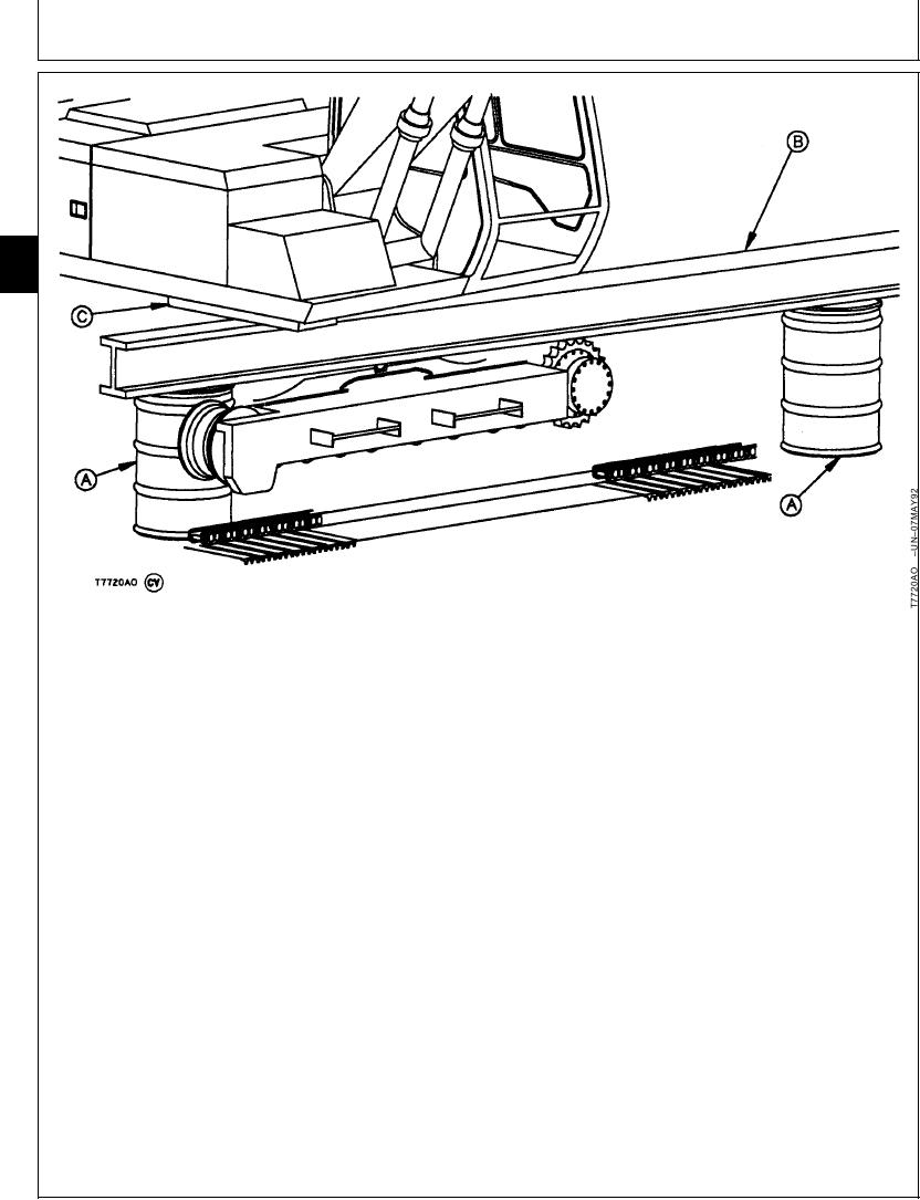
A--DFT1089 Barrel
C--Hardwood Block (As
Support (2 used)
Required)
B--3.7 m (12 ft) Length of
W8 x 35 lb Wide Flange
Beam
16. Tighten any of the swing bearing-to-upperstructure
11. Raise machine just enough to remove hardwood
cap screws that could not be tightened.
blocks (C), wide flange beam (B), and barrel
supports (A).
Swing Bearing-to-Upperstructure Cap Screw--Specification
12. Lower machine so lower track rollers and front
Torque................................................................. 1230 Nm (900 lb-ft)
idler are on track chain.
17. Install track chains. (See procedure in Group
13. Remove bridge planks and barrel supports from
0130).
other side.
18. Adjust track sag. (See procedure in Group 0130.)
14. Turn upperstructure to other side and raise
machine just enough to remove hardwood blocks
between roller and track chain.
15. Lower machine so lower track rollers and front
idler are on track chain.
CED,OUOE027,237
1915MAY984/4
21-27