
TM 5-3805-281-24-2
Mechanical Drive Elements
5. Install cover (B).
6. Install stop (A).
7. Connect lines.
8. Connect negative battery cable.
43
9. Remove chain from boom cylinder.
4350
26
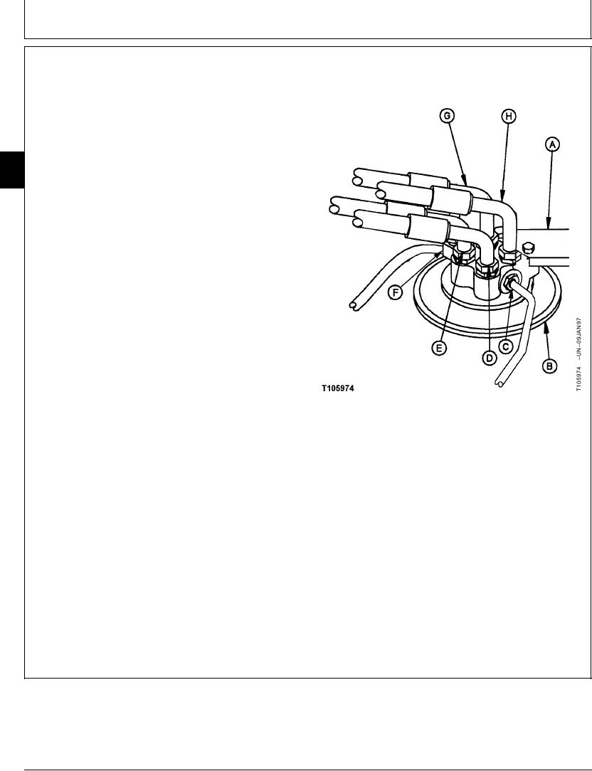
A--Stop
B--Cover
C--P1-to-Proportional Solenoid Valve "SH" Port
Line
D--Port 2-to-Right Propel Section Bottom Port
(Reverse) Line
E--Port 4-to-Left Propel Section Bottom Port
(Reverse) Line
F--Port D-to-Return Manifold
G--Port 3-to-Left Propel Section Top Port
(Forward) Line
H--Port 1-to-Right Propel Section Top Port
(Forward) Line
Continued on next page
CED,OUOE027,237
1915MAY982/4
21-25