
TM 5-3805-281-24-2
Mechanical Drive Elements
REMOVE AND INSTALL SWING BEARING
1. Remove upperstructure. (See procedure in this group.)
CAUTION: The approximate weight of swing
bearing is 500 kg (1102 lb).
43
Swing Bearing--Specification
4350
29
Weight.......................................................... 500 kg (1102 lb) approximate
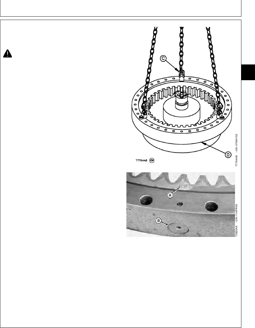
2. Connect swing bearing to hoist using lifting brackets
(C) such as JT01748 Lifting Brackets.
3. Remove cap screws (D). Remove bearing.
4. Replace upper and lower seals, steel balls, and
spacers as necessary. (See procedures in this group.)
5. Clean mating surfaces of swing bearing,
upperstructure, and undercarriage using cure primer.
6. Apply plastic gasket to mating surfaces of swing
bearing, upperstructure, and undercarriage.
IMPORTANT: The tooth marked with the letter "G" or
"S", or equivalent is the starting and
stopping point for the hardening
process. The tooth and bearing loading
plug must be installed on right side of
machine so use of that part of swing
bearing is minimized.
7. Install swing bearing on undercarriage so tooth (A)
marked "G" or "S", or equivalent and bearing loading
plug (B) is to right side of machine.
8. Install cap screws (D) and tighten.
Swing Bearing-to-Undercarriage Cap Screw--Specification
A--Tooth
Torque ....................................................................... 1230 Nm (900 lb-ft)
B--Loading Plug
C--Lifting Bracket (3 used)
9. Apply multi-purpose grease to swing bearing teeth and
D--Cap Screw (36 used)
pinion shaft. (See Track Adjuster, Working Tool Pivot,
Swing Bearing, and Swing Bearing Gear Grease in
Group 0004.)
CED,OUOE027,236
1915MAY981/1