
TM 5-3805-281-24-2
Mechanical Drive Elements
43
4350
22
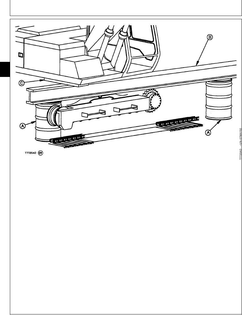
A--DFT1089 Barrel
C--Hardwood Block (As
Support (2 used)
Required)
B--3.7 m (12 ft) Length of
W8 x 35 lb Wide Flange
Beam
NOTE: For maximum support, the barrel supports
9. Lower machine so main frame and corner of cab is
must be positioned so the beam is under the
on the beam.
main frame and corner of cab as far as
possible.
Check that bottom of main frame is 1500 mm (59
in.) off the floor and level. Keep height to a
Install hardwood blocks (C) as needed to
maximum of 51 mm (2 in.) more than specified.
make up for any unevenness.
Bottom of Main Frame-to-Floor Clearance--Specification
8. Put DFT1089 Barrel Supports (A) and a 3.7 m (12
Height........................................................ 1500 mm (59 in.) minimum
ft) length of W8 x 35 lb Wide Flange Beam (B)
Height....................................................... 1550 mm (61 in.) maximum
under main frame at right boom cylinder and right
corner of cab.
Continued on next page
CED,OUOE027,235
1915MAY983/7
21-21