
TM 5-3805-281-24-2
Mechanical Drive Elements
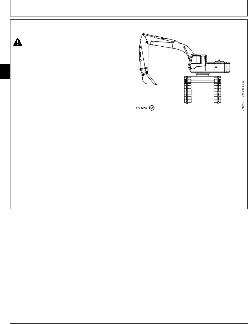
REMOVE UPPERSTRUCTURE
CAUTION: Keep the angle between boom and
arm at 90--100 to prevent machine from sliding
backwards.
NOTE: Procedure requires two technicians. The cement
43
floor must be a minimum of 102 mm (4 in.) thick.
4350
Area must be large enough so the upperstructure
20
can be turned 180 with the angle between boom
and arm at 90--100 and the tracks laid out flat
on the floor.
1. Park machine with boom to left side (cab side toward
sprocket) of undercarriage. Move arm so angle
between boom and arm is 90--100.
2. Disconnect tracks and lay out flat on floor to sprocket
end of undercarriage. (See procedure in Group 0130.)
NOTE: To make removal of main frame-to-swing bearing
cap screws easier after machine is raised into
position, loosen the cap screws one turn at this
time.
3. Turn upperstructure to right side. Raise right side of
undercarriage using boom down function.
Continued on next page
CED,OUOE027,235
1915MAY981/7