
TM 5-3805-294-10
0003
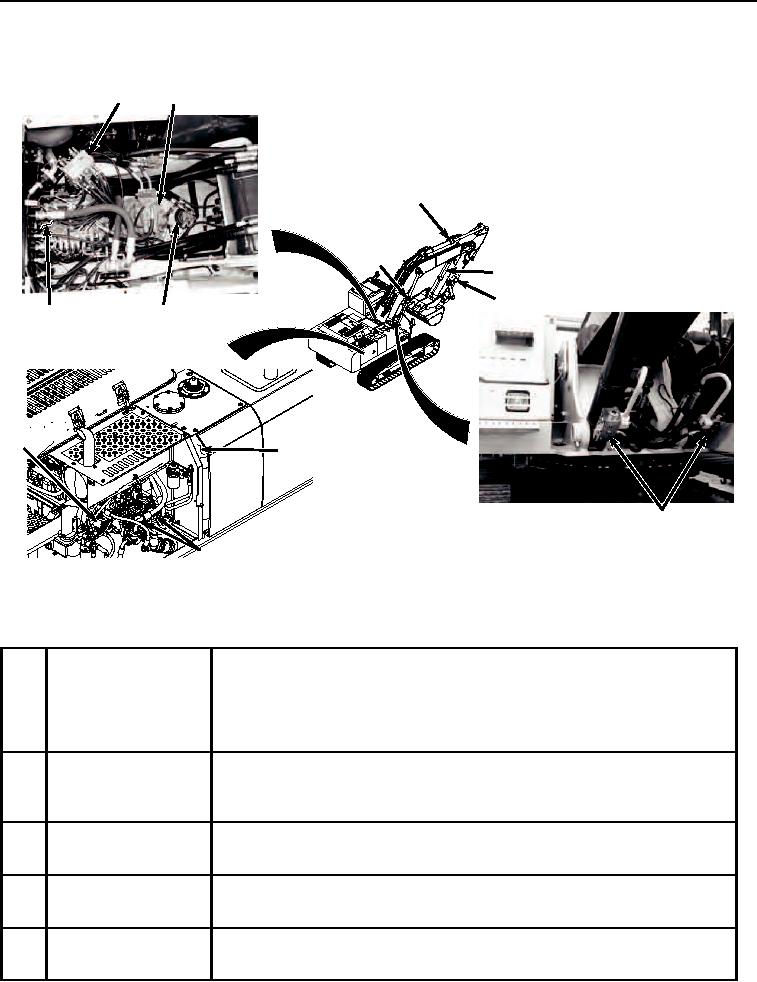
Hydraulic System - Continued
10
11
14
13
15
16
9
12
7
8
17
HYEX01512
6
Figure 3. Hydraulic System Components Continued.
Table 3. Hydraulic System Components Continued.
10
Pilot Signal Manifold
The pilot signal manifold is in the pilot system between the pilot control valves
and the control valve and regulators. The manifold receives a pilot signal from
the pilot control valves and sends the signal on multiple paths simultaneously
so there is little lag between operation of the pilot control valves, pump stroke,
and function movement.
11
Swing Motor
The swing motor uses hydraulic pressure supplied by the pumps to make the
upper structure rotate. It has a spring-applied hydraulically-released swing
brake. The swing brake engages as soon as the swing controls are released.
12
Rotary Manifold
The rotary manifold allows the upper structure of the machine to rotate relative
to the undercarriage while still supplying hydraulic oil to the travel motors.
13
Boom Cylinders
The boom cylinders are attached to the main frame and the boom. When
activated they raise and lower the boom.
14
Arm Cylinder
The arm cylinder is attached between the boom and the arm. When activated,
this cylinder moves the arm in and out.