TM 5-3805-294-10
0003
Hydraulic System - Continued
Table 3. Hydraulic System Components Continued - Continued.
15
Hydraulic Thumb
The hydraulic thumb cylinder is attached between the arm and the thumb.
Cylinder
When activated, this cylinder extends and retracts the hydraulic thumb. The
hydraulic thumb cylinder circuit can be closed to provide the hydraulic power
to operate the crush-all, breaker, compactor and deep dig arm accessories.
16
Bucket Cylinder
The bucket cylinder is attached between the arm and the quick latch. When
activated, this cylinder extends and curls the bucket or attachments.
17
Load Holding Valves
Reduced leakage valves are used in the boom head-end circuit and arm rod-
end circuit. The function of a reduced leakage valve is to reduce cylinder drift
by stopping leakage from the cylinder back through the control valve.
Powertrain
21
18
20
19
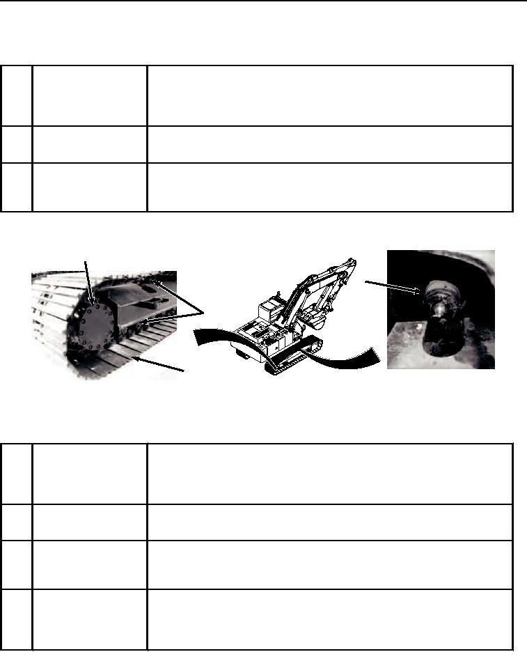
HYEX01513
Figure 4.
Powertrain Components.
Table 4.
Powertrain Components.
18
Track Chain Adjuster
The track chain adjuster is located between the frame and the track chain idler.
Grease is added or removed to adjust the track sag. The recoil spring is located
with the track chain adjuster and absorbs shocks to the tracks and track chain
idler.
19
Track
The track assembly consists of the chain and shoes. The travel motor drives
the track to move the machine.
20
Rollers
The machine has two carrier rollers and nine lower track rollers on each side
of the machine. The rollers guide the tracks and keep the tracks in contact with
the ground.
21
Travel Motor
The travel motors are located inside the tracks to prevent damage during
operation. The travel system has a spring-applied hydraulically-released
parking brake. The parking brake engages as soon as the travel controls are
released.

