
TM 5-3805-294-23-4
0496
INSTALLATION - Continued
5.
Install two brackets (Figure 8, Item 27) to four screws (Figure 8, Item 4).
6.
Install two clamps (Figure 8, Item 26) and (Figure 8, Item 25) to screws (Figure 8, Item 4).
7.
Ensure screws (Figure 8, Item 4) are still hooked into frame (Figure 8, Item 28).
8.
Install two washers (Figure 8, Item 24), eight nuts (Figure 8, Item 23), and four spacers (Figure 8, Item 22) to
screws (Figure 8, Item 4).
9.
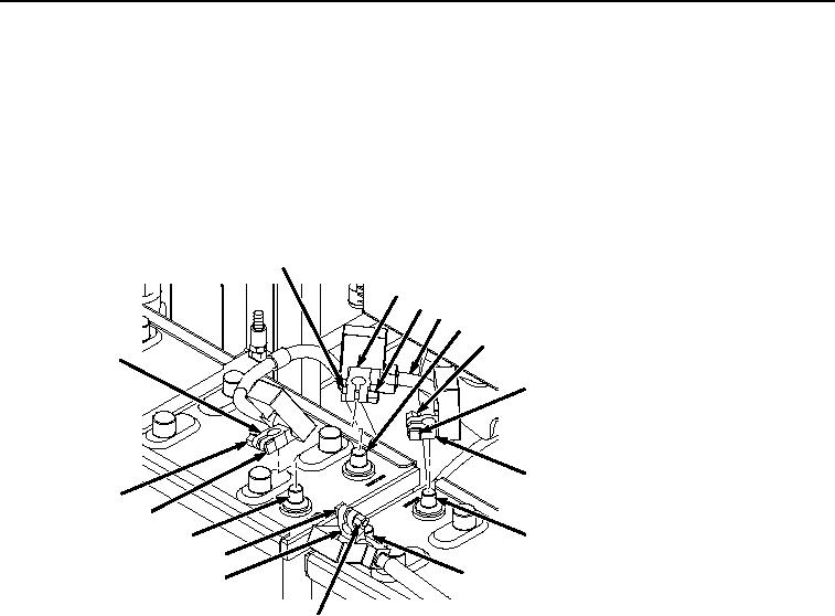
Install positive battery terminal clamp (Figure 9, Item 20) to positive battery terminal (Figure 9, Item 21).
10
11
9
17
12
13
7
14
15
5
6
16
8
19
21
20
18
HYEX00114
Figure 9. Battery Cables Installation.
10.
Tighten nut (Figure 9, Item 18) to screw (Figure 9, Item 19) on positive battery terminal clamp (Figure 9, Item
20).
11.
Install battery jumper cable (Figure 9, Item 17) by installing negative battery terminal clamp (Figure 9, Item 15)
to negative battery terminal (Figure 9, Item 16).
12.
Tighten nut (Figure 9, Item 13) to screw (Figure 9, Item 14) on positive battery terminal clamp (Figure 9, Item
15).
13.
Finish installing battery jumper cable (Figure 9, Item 17), by installing positive battery terminal clamp (Figure
9, Item 11) to positive battery terminal (Figure 9, Item 12).
14.
Tighten nut (Figure 9, Item 9) to screw (Figure 9, Item 10) on positive battery terminal clamp (Figure 9, Item
11).
15.
Install negative battery terminal clamp (Figure 9, Item 7) to negative battery terminal (Figure 9, Item 8).
16.
Tighten nut (Figure 9, Item 5) to screw (Figure 9, Item 6) on negative battery terminal clamp (Figure 9, Item
7).