
TM 5-3805-294-23-4
0622
INSTALLATION - Continued
21
20
10
22
18
24 25
14
13
21
19
15
7
16
16
17
4
1
24
23
10
11
12
7
9
8
4
6
5
2
3
1
HYEX02941
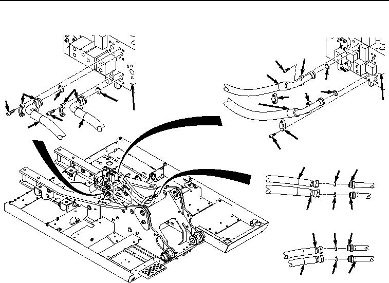
Figure 2. Hose Installation.
2.
Install hose (Figure 2, Item 7) and O-ring (Figure 2, Item 25) to main control valve (Figure 2, Item 16) with two
clamp halves (Figure 2, Item 24) and four screws (Figure 2, Item 23).
3.
Lightly lubricate O-ring (Figure 2, Item 22) with clean oil.
4.
Install hose (Figure 2, Item 10) and O-ring (Figure 2, Item 22) to main control valve (Figure 2, Item 16) with
two clamp halves (Figure 2, Item 21) and four screws (Figure 2, Item 20).
5.
Lightly lubricate O-ring (Figure 2, Item 19) with clean oil.
6.
Install hose (Figure 2, Item 1) and O-ring (Figure 2, Item 19) to main control valve (Figure 2, Item 16) with two
clamp halves (Figure 2, Item 18) and four screws (Figure 2, Item 17).
7.
Lightly lubricate O-ring (Figure 2, Item 15) with clean oil.
8.
Install hose (Figure 2, Item 4) and O-ring (Figure 2, Item 15) to main control valve (Figure 2, Item 16) with two
clamp halves (Figure 2, Item 14) and four screws (Figure 2, Item 13).
9.
Lightly lubricate O-ring (Figure 2, Item 12) with clean oil.
10.
Install O-ring (Figure 2, Item 12) to line (Figure 2, Item 11).
11.
Install hose (Figure 2, Item 10) to line (Figure 2, Item 11).
12.
Lightly lubricate O-ring (Figure 2, Item 9) with clean oil.
13.
Install O-ring (Figure 2, Item 9) to line (Figure 2, Item 8).
14.
Install hose (Figure 2, Item 7) to line (Figure 2, Item 8).