
TM 5-3805-294-23-4
0623
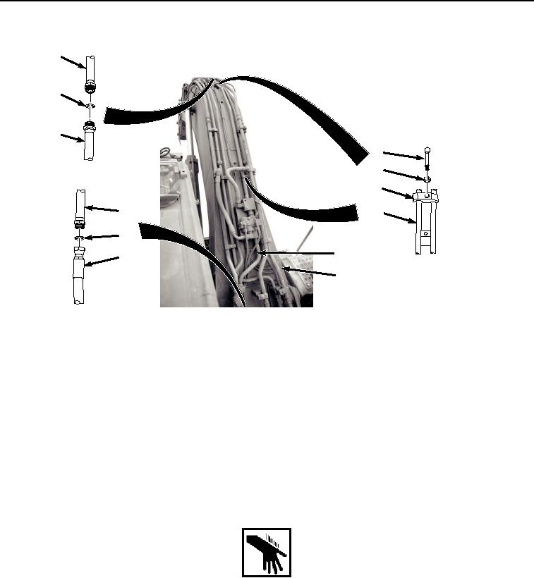
RIGHT SIDE LINE REMOVAL - Continued
13
14
11
15
16
17
11
11
12
11
10
9
HYEX01778
Figure 2. Right Side Line Removal.
2.
Remove O-ring (Figure 2, Item 12) from line (Figure 2, Item 11). Discard O-ring.
3.
Remove hose (Figure 2, Item 13) from line (Figure 2, Item 11).
4.
Remove O-ring (Figure 2, Item 14) from line (Figure 2, Item 11). Discard O-ring.
5.
Remove two screws (Figure 2, Item 15), washers (Figure 2, Item 16), and clamps (Figure 2, Item 17) from line
(Figure 2, Item 11).
6.
Remove line (Figure 2, Item 11) from boom (Figure 2, Item 9).
END OF TASK
RIGHT SIDE LINE INSTALLATION
WARNING
NOTE
Install hoses and fittings as noted during removal.
Install clamps as noted during removal.
1.
Install line (Figure 3, Item 11) to boom (Figure 3, Item 9) with two screws (Figure 3, Item 15), washers (Figure
3, Item 16), and clamps (Figure 3, Item 17).