
TM 5-3805-294-23-4
0623
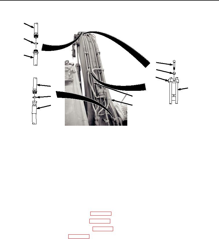
LEFT SIDE LINE INSTALLATION - Continued
4
5
2
6
7
8
2
2
3
2
1
9
HYEX01777
Figure 4. Left Side Line Installation.
2.
Lightly lubricate O-ring (Figure 4, Item 5) with clean oil.
3.
Install O-ring (Figure 4, Item 5) to line (Figure 4, Item 2).
4.
Install hose (Figure 4, Item 4) to line (Figure 4, Item 2).
5.
Lightly lubricate O-ring (Figure 4, Item 3) with clean oil.
6.
Install O-ring (Figure 4, Item 3) to line (Figure 4, Item 2).
7.
Install hose (Figure 4, Item 1) to line (Figure 4, Item 2).
END OF TASK
FOLLOW-ON MAINTENANCE
1.
Install auxiliary circuit supply boom lines. (WP 0633)
2.
Install auxiliary circuit return boom lines. (WP 0637)
3.
Release vacuum from hydraulic reservoir. (WP 0620)
4.
Install negative battery cable. (WP 0521)
5.
Perform the Standard Follow-On Maintenance Instructions. (Volume 3, WP 0384)
END OF TASK
END OF WORK PACKAGE