
TM 5-3805-294-23-4
0624
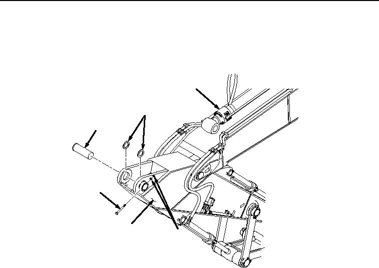
REMOVAL - Continued
8.
Start machine (TM 5-3805-294-10).
9.
Remove two nuts (Figure 4, Item 6) and bolt (Figure 4, Item 7) from arm (Figure 4, Item 3) and pin (Figure 4,
Item 8).
2
9
8
7
3
6
HYEX03448
Figure 4.
Pin Removal.
10.
Remove pin (Figure 4, Item 8) from arm cylinder (Figure 4, Item 2) and arm (Figure 4, Item 3).
11.
Fully retract arm cylinder (Figure 4, Item 2).
12.
Remove two shims (Figure 4, Item 9) from arm (Figure 4, Item 3).
13.
Shut machine off (TM 5-3805-294-10).
14.
Relieve hydraulic system pressure. (Volume 5, WP 0767)
15.
Remove hose (Figure 5, Item 10) from fitting (Figure 5, Item 11).