
TM 5-3805-294-23-4
0624
REMOVAL
25
26
13
27
28
34
29
26
25
30
35
36
31
33
2
32
HYEX03451
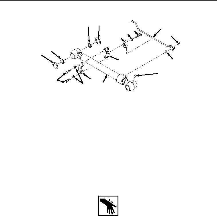
Figure 10.
Pipe and Clamp Removal.
27.
Remove bolt (Figure 10, Item 27), lockwasher (Figure 10, Item 28), and clamp (Figure 10, Item 29) from band
(Figure 10, Item 30) and line (Figure 10, Item 13). Discard lockwasher.
28.
Remove two bolts (Figure 10, Item 31), lockwashers (Figure 10, Item 32), clamp (Figure 10, Item 33), and band
(Figure 10, Item 30) from arm cylinder (Figure 10, Item 2). Discard lockwashers.
29.
Remove four screws (Figure 10, Item 34), line (Figure 10, Item 13), and O-ring (Figure 10, Item 35) from arm
cylinder (Figure 10, Item 2). Discard O-ring.
30.
Remove fitting (Figure 10, Item 36) from arm cylinder (Figure 10, Item 2).
END OF TASK
INSTALLATION
WARNING
NOTE
Install hoses, fittings, and shims as noted prior to removal.
Remove caps and plugs as hoses and fittings are installed.
Install tie wraps as required.
1.
Install fitting (Figure 11, Item 36) to arm cylinder (Figure 11, Item 2).