
TM 5-3805-294-23-4
0624
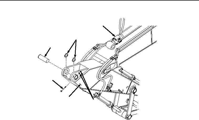
INSTALLATION - Continued
2
9
8
7
3
6
HYEX03448
Figure 17.
Pin Installation.
22.
Install two shims (Figure 17, Item 9) to arm (Figure 17, Item 3) and arm cylinder (Figure 17, Item 2).
23.
Install pin (Figure 17, Item 8) to arm cylinder (Figure 17, Item 2) and arm (Figure 17, Item 3).
24.
Install bolt (Figure 17, Item 7) and two nuts (Figure 17, Item 6) to arm (Figure 17, Item 3) and pin (Figure 17,
Item 8).
25.
Tighten two nuts (Figure 17, Item 6) against each other to 555 lb-ft (752 Nm) allowing bolt (Figure 17, Item 7)
to spin freely.
26.
Remove suitable lifting device (Figure 18, Item 5) from arm cylinder (Figure 18, Item 2).