
TM 5-3805-294-23-4
0624
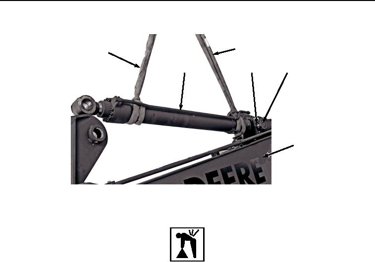
INSTALLATION - Continued
5
5
2
23, 24
22, 25
1
HYEX03472
Figure 12.
Arm Cylinder Installation.
WARNING
Arm cylinder weighs 640 lb (290 kg). Do not attempt to lift or move arm cylinder without the
aid of an assistant and suitable lifting device. Failure to comply may result in injury or death
to personnel.
9.
With the aid of an assistant and suitable lifting device (Figure 12, Item 5), position arm cylinder (Figure 12,
Item 2) and two shims (Figure 12, Item 25) to boom (Figure 12, Item 1).
10.
Install pin (Figure 12, Item 22) to arm cylinder (Figure 12, Item 2) and boom (Figure 12, Item 1).
11.
Install bolt (Figure 12, Item 24) and two nuts (Figure 12, Item 23) to boom (Figure 12, Item 1) and pin (Figure
12, Item 22).
12.
Tighten two nuts (Figure 12, Item 23) against each other to 555 lb-ft (752 Nm) allowing bolt (Figure 12, Item
24) to spin freely.
13.
Install line (Figure 13, Item 21) to boom (Figure 13, Item 1) with three bolts (Figure 13, Item 18), washers
(Figure 13, Item 19), and clamps (Figure 13, Item 20).