
TM 5-3805-294-23-4
0624
REMOVAL - Continued
Tag and mark hoses, fittings, and shims prior to removal to ensure proper installation.
Note position of each tie wrap and remove as required.
17.
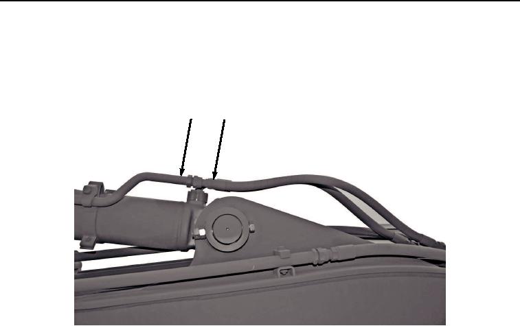
Remove hose (Figure 6, Item 12) from line (Figure 6, Item 13).
13
12
HYEX03445
Figure 6. Hydraulic Hose Removal.
18.
Remove four screws (Figure 7, Item 14), two clamp halves (Figure 7, Item 15), hose (Figure 7, Item 16), and
O-ring (Figure 7, Item 17) from arm cylinder (Figure 7, Item 2). Discard O-ring.