
TM 5-3805-294-23-4
0624
INSTALLATION - Continued
26
13
27
28
34
29
26
30
35
36
33
31
2
32
HYEX03471
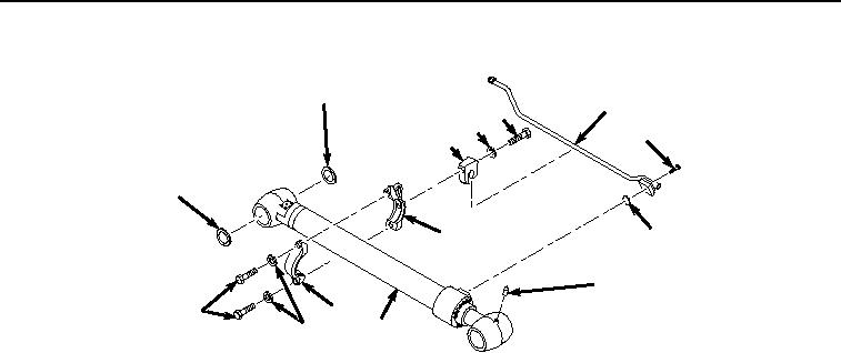
Figure 11.
Pipe and Clamp Installation.
2.
Lightly lubricate O-ring (Figure 11, Item 35) with clean oil.
3.
Install O-ring (Figure 11, Item 35) and line (Figure 11, Item 13) to arm cylinder (Figure 11, Item 2) with four
screws (Figure 11, Item 34).
4.
Tighten four screws (Figure 11, Item 34) to 130 lb-ft (176 Nm).
5.
Install clamp (Figure 11, Item 33) and band (Figure 11, Item 30) to arm cylinder (Figure 11, Item 2) with two
lockwashers (Figure 11, Item 32) and bolts (Figure 11, Item 31).
6.
Install clamp (Figure 11, Item 29) to band (Figure 11, Item 30) and line (Figure 11, Item 13) with lockwasher
(Figure 11, Item 28) and bolt (Figure 11, Item 27).
7.
Install two seals (Figure 11, Item 26) to arm cylinder (Figure 11, Item 2).
8.
Attach suitable lifting device (Figure 12, Item 5) to arm cylinder (Figure 12, Item 2) with two points of lift at each
end of cylinder barrel.